Channel coding theory: An introduction and comparison of block, Convolutional, Turbo and low-density parity-check (LDPC) codes
In this post, a brief introduction about channel coding theory is presented. The comparison of convolutional, TURBO and LDPC codes for use in global navigation satellite system (GNSS) signals is also presented.

In this post, a brief introduction about channel coding theory is presented. The comparison of convolutional, TURBO and LDPC codes for use in global navigation satellite system (GNSS) signals is also presented.
Channel coding is instrumental for robust wireless signal transmission.
Unlike cable transmission that use a physical channel, in wireless transmission, signals are travel over the air or vacuum (space) environments that are a non-guided media (there is no physical link in the transmission).
Hence, the non-guided media, such as air and vacuum environments, adds significant noises to transmitted data. That is, wireless transmission is often called transmission via noisy channel.
This noisy channel causes some of the bits of a transmitted message are flipped or changed. These bit changes cause the received version of the message to be different with the original transmitted message. That is, the noisy channel causses message errors at a receiver.
To overcome received message errors due to bit flipping or changes during transmission in a noisy wireless channel, the use of channel coding is one of the most effective ways to solve this problem. With channel coding, the error bits in a received message can be corrected so that the original message can be recovered. Due to this reason, the application is often called “error correcting code”.
For global navigation satellite system (GNSS), such as the well-known global positioning system (GPS), channel coding implementation is very useful to increase the reliability of transmitted navigation signals.
In this post, we will briefly explain block, convolutional, TURBO and low-density parity-check (LDPC) codes. And then, a brief comparison study of these coding performance is presented.
We recommend book “Iterative error correction: Turbo, Low-Density Parity-Check and Repeat-Accumulate codes” by Prof. Sarah Johnson about channel coding theory [1]. I found this book is very clear and detail in its explanation about channel coding theory.
Let us go to discuss them!
READ MORE: Beware of reading signal-to-noise ratio (SNR) from power spectral density (PSD) plot.
Channel coding: A brief explanation
Channel encoding
Channel coding is the application of message encoding at transmitter and message decoding at receiver where during the decoding process, message bit errors will be corrected.
The main aim of channel coding is to find the best message encoding-decoding method to detect and correct message bit errors. The best message encoding-decoding method is the one that has high code rate while having good error correcting capability.
It is common that good error correcting capability is a trade-offwith the amount of code rate and processing (message encoding-decoding) complexity in wireless transmission [1].
The general form of channel coding implementation is as follow.
A message with a number of $K$ bits is encoded (with a specific coding method, such as block code or convolutional code) with additional bits. These additional bits create redundanciesin the message and reduce the code rate, that is the communication will be below its maximum channel capacity.
The number of bits of the encoded message (with length of $K$ bits) is $N$ bits. Hence, $K$ is called the message length, $N$ is the code length or codeword $c$ and $N>K$.
The code rate $r$ of a message is then defined as $r=K/N$. That is, with the additional bits (redundancy) the code rate is slower and will be $< 1$. Code rate $r$ defines the amount of information or bits redundancy added into original message bits.
For example, code rate of $1/2$ means that from the total received codeword bits, only half of them contain information.
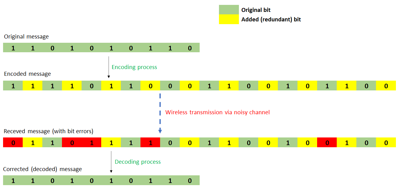
Figure 1 below shows an illustration of channel coding implementation on a wireless transmission. In Figure 1, the original message is encoded (with a certain channel coding method) and have additional bits to the message.
These additional bits are redundancy bits, but they are used to correct error bits when the message is received.
In figure 1, the code rate is $1/2$ because the total message bit $k=10$ and the total codeword $c=20$. Hence the code rate $r=10/20=1/2$. From this condition, the transfer rate of the message is reduced to be a-half from the original capacity.
This reduced capacity is paid-off by the ability to increase the reliability of the message transmission (by being able to correct errors on the message bits).
In general, channel coding is divided into: Block codeand convolutional code.
- Block codes
In this block code scheme, binary bits with length $k$ are mapped to code word $c$ with length $n$. The main characteristic of block code is that the mapping (by an encoder) from the binary message bits to the code word is independent.
That is, the output of the encoder solely depends on the current input sequence of the binary bits and do not depend on the previous input sequence of the binary bits.
In other words, the binary bits sequence is mapped into the code words in a fixed way regardless of the previous bit in the binary sequence.
The most common type of block is Linear code, such asHamming code. A special form of block code is LDPC code.
Cyclic-redundancy check (CRC) code is a type of block code to add redundant bits to verify whether a message has a bit error or not. But, it is not for correcting the error bits.
- Convolutional code
The main characteristic of convolutional code is that the mapping (by an encoder) from original binary bits to a code word is not independent. That is, the output of the encoder not only depends on the current input sequence of the binary bits, but also depends on the previous input sequence of the encoderbits.
A convolutional code works as a finite-state machine [1]. That is, this type of code takes a continuous stream of binary (message) bits and produces a continuous stream of code word (output) bits.
A convolutional encoder has a memory of past input bits that is stored in the encode state.
Convolutional code is the basis for TURBO code.
Channel decoding
Commonly, decoding of a block code is non-iterative. That is the decoding is a direct block decoding computation. This direct computation requires low computational capacity.
Meanwhile, for convolutional code, an iterative decoding algorithm is required [1]. Although, this iterative decoding requires high computation capacity, it has an advantage over a direct block decoding computation method.
The main advantage of iterative coding method is that it can significantly outperforms the block decoding performance and can closely reach the theoretical performance limit set by Shannon’s theorem.
Special for LDPC code, this code is quite unique. LDPC is a type of block doe. However, LDPC requires an iterative decoding method to be able to correct the bit errors of a message.
- Grammar Rules: Everything you need to know but never learnt in school – A book about how to make efficient and concise sentences to writing with military precision!
Block (linear) code
Linear code is a block code that has any linear combination of two codewords is a codeword. For binary case, the sum of any two codewords is a codeword [2].
The codeword $c$ of a linear block code is obtained via a direct matrix calculation between a message bit $m$ and a generator matrix $G$[2]:

For linear block code, an important parameter that directly affects its error correcting capability is its Hamming distance.
Hamming distance is the minimum distance of a code in a codeword. That is, a minimum hamming-defined distance between two different codeword.
The minimum (Hamming) distance $d_{min}$ of a code is defined as:

And for linear block code, the minimum distance is identical with the minimum weight of code $w_{min}$ (the minimum number of 1 in a non-zero codeword) and is defined as:

- Scientific Calculator - the well-known and practical Casio FX-83GTCW
Convolutional codes
Convolutional code’s encoder has memories that store past inputs. The convolutional code depends on the value of the current message bit(to encode) and the values in its encoder states.
In convolutional code, the transmission can be done before all message bits have been encoded (the codeword has not yet completed).
Unlike for block code, in block code the transmission can be performed only when all message bits have been encoded (the codeword has been completed).
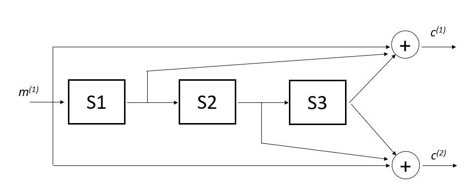
Figure 2 below shows the example of convolutional code and its encoder states. In figure 2, the encoder “block” (state) represents the element of shift-registers and the “circle” represents modulo-2 sum.
At time $t$, the encoder input is a message bit $m ^{1}$ and the outputs of the encoder are $c ^{1}$ and $c ^{2}$. that is, the encoder has a code rate $r$ of $1/2$.
The codeword $c$ is then obtained by interleaving the stream $c ^{1}$ and $c ^{2}$.
Hence, the codeword $c$ will be:

Meanwhile, the state $S$ of the encoder is given by:

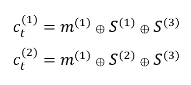
From figure 2 below, $c ^{1}$ and $c ^{2}$ are obtained from:
Reader can refer to [1] for more detailed explanations about recursive convolutional code, puncturing and Trellis diagram.
TURBO codes
TURBO code is a subset of convolutional code as this code is constructed from two convolutional code building blocks.
The other name of TURBO code is parallel concatenated convolutional codes (PCCC). In an optimal condition, TURBO code has an exceptional bit error correction performance that can reach near Shannon limit [1].
In TURBO code, its encoding process should be done per code block following the interleaver length.
For example, if the total message bit length is $100$ and the interleaver length is $20$. Then, the encoding should be performed per 20 bits.
TURBO coding is a coding method that combine two simple convolutional codes. These two simple codes are connected via a large length pseudorandom interleave to create a close-to-random structure and large block length [2].
TURBO code is one of code that can archive or close to achieve the maximum capacity of a channel.
One of the main motivations of TUBRO coding is to have a random code with some structures to reduce decoding complexity and to make a decoding of a large code to be feasible. This randomness is required to follow Shannon’s theorem saying that codes that can achieve a channel capacity should be random.
The randomness property is obtained from a long pseudo-random interleaver.
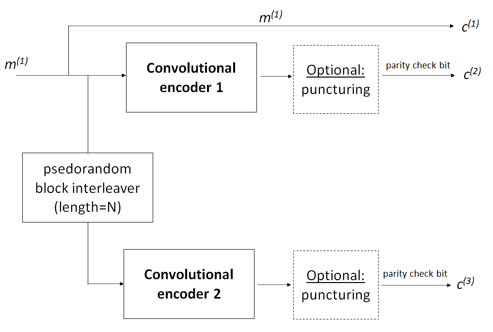
Figure 3 above presents the structure of TURBO code. From figure 3, the structure shows a TURBO code with code rate of 1/3. However, TURBO code rate can be adjusted. For example, to get 1/2 code rate of TURBO code, the output $c_{2}$ and $c_{3}$ can be taken interchangeably for every other symbol.
As shown in figure 3 above, in TURBO code, a message bit goes to convolutional encoder 1 and 2. Before going to the convolutional encoder 2, the message bit passes an interleaver to add a randomness to the code and then goes to the convolutional encoder 2.
From the convolutional encoder 1 and 2, codes then go to a puncturing process. but, this puncturing process is optional. Many of TURBO codes do not have puncturing processes.
Puncturing is a method to reduce the convolutional code rate by skipping (not transmitting) some subset of codeword over [1]. This is an optional step in both convolutional and TURBO code.
READ MORE: The problematic aspect of number crunching in programming: Case study in GNSS calculations.
Low-Density Parity-Check (LDPC) codes
LDPC code is a type of code that is characterised by a sparse parity-check matrix. LDPC code is a type of block code, but it requires an iterative algorithm for decoding.
There are district differences between a Hamming block code and LDPC block code. Hamming codes are characterised by short codes and very well-structured with a known error correction ability. Meanwhile, LDPC codes are characterised by long codes and pseudo-randomly constructed with an expected error correction performance (not known and fixed like in the case on Hamming codes).
A LDPC code is a linear combination of parity-check equations. These parity check equations are defined by a parity-check matrix representation. The best graphical representation of LDPC codes is by using Tanner graph [1].
The basic model of LDPC codes is:

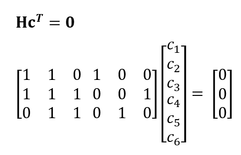
Where H is the parity check matrix. Each row of matrix H represents a parity check equation and each column of matrix Hcorresponds to a bit (code) in a codeword.
For example:
Suppose we have a codeword (obtained after implementing LDPC encoder to message bits) with a 6-length vector:

And satisfy a pre-determined parity-check equations (rule) of:
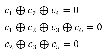
Then, the LDPC model becomes:
- Scientific Calculator - the well-known and practical Casio FX-83GTCW
A brief comparison: convolutional, TURBO and LDPC code performances for GNSS signal applications
Related to GNSS, in this case GPS signal, there are specific channel coding method proposed or potentially can be used for GPS or other GNSS signals.
The proposed coding methods are:
- TURBO code. This code is a recommendation from Space Data System Standards: TM Synchronization and channel coding (see Figure 6-2, page 6-5) [3]
- LDPC code. This code is a recommendation from “NAVSTAR GPS Space Segment/User Segment L1C Interfaces” (see Figure 3.2-5, page 22) [4]
In this section, a brief performance comparison of these codes is presented.
TURBO code
The structure of the TURBO code in this comparison study is based on CCSDS [3].
Figure 4 below shows the structure of the studied TURBO code. The code rate of the studied TURBO code is $1⁄3$ without puncturing.
TURBO encoding
The encoding process follow the method based on Trellis diagram [1]. The structure of the code word from message y:

will be:

The encoding process is that a message (input) bit enters the first encoder and directly becomes the output $c_{1}$. The same bit also enters the convolutional encoder 1 (switch down) and convolves with the encoder state to output the second codeword $c_{2}$.
The same bit also enters the interleaver where the bit positions are interchanged (interleaved). This interchanging process is to simulate randomness of noise channels. TURBO code should be processed block-by-block following the length of the interleaver.
The interleaving operation should be performed for all the message bits. The position permutation $\phi(s)$ is calculated as [3]:
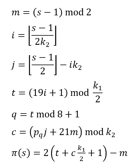
Where $p_{q}$ is one of the following eight prime integers:

To make all the encoder states back to zero and the encoding process stops, the switch of the encoder is up (figure 4 below).
TURBO decoding
a soft-decision iterative decoding algorithm should be used. Then, BCJR decoding algorithm is used.
BCJR is a decoding algorithm for convolutional code and is based on maximum-a-posteriori (MAP) estimation. For detailed information about BCJR algorithm, readers can refer to [1].
The computational cost for each BCJR algorithm iteration is high, but it can converge within few iterations.
Convolutional code
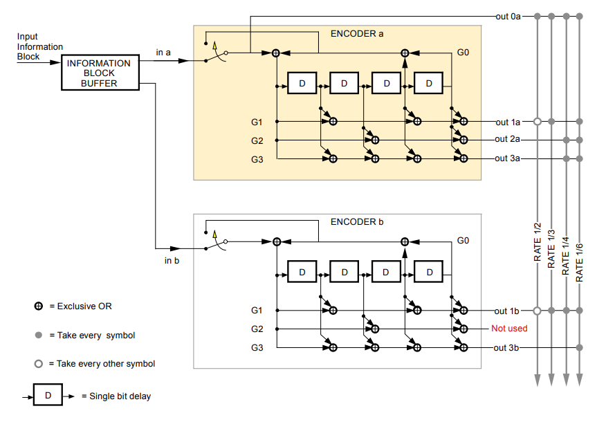
For this comparison study, the structure of the convolutional code uses the convolutional encoder 1 of the TURBO code in figure 4 above [3].
Convolutional encoding
The encoding process of this convolutional code follows the standard method using the Trellis diagram (details about this diagram can be found in [1]).
The code rate is $1/2$. That is, the encoding output is the original message bit $out0a$ and one of the encoder output $out 1a$.
Each message bit goes to the encoder and updates the encoder output until the output bit is obtained. This process is performed iteratively until all the encoder states have zero values.
The switch in figure 5 below is up to set all the internal encoder state to be zero after four-time steps.
Convolutional decoding
Vitterbi algorithm is used to decode the convolutional code with this structure. For detailed procedure to implement Vitterbi algorithm, please see [1]. Vitterbi algorithm is based on maximum likelihood (MLE) estimation.
Note that Vitterbi algorithm is based on 0 and 1 bit. hence, all received codeword bit should be converted to either 0 or 1 depending on a detector threshold. Usually, above 0.5 is 1 and otherwise.

LDPC code
The structure of the LDPC code [4] for comparison has a code rate $r$ of $1/2$. That is, the length of the output codeword $c$ after encoding is two times the length of an encoded message length.
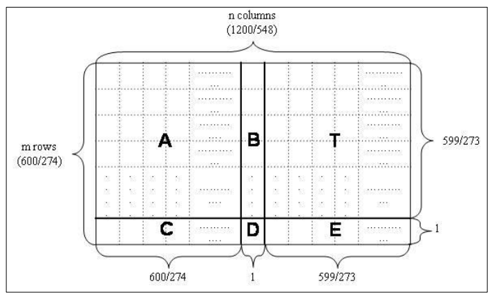
Figure 6 below shows the structure of the H matrix of the LDPC code [4]. Since the matrix is a $600 \times 1200$ matrix, the total parity-check equation is 600 and the codeword length is 1200 bits. Hence, the message length should be 600 bits.
The parity check H matrix consists of six sub-sections: A, B, C, D, E, T. The structures of these sub-section elements are as follow [4]:
- Matrix A. Size: 599x600. See (see Table 6.2-2 in [4])
- Matrix B. Size: 599×1. See (see Table 6.2-3 in [4])
- Matrix C. Size: 1×600. See (see Table 6.2-4 in [4])
- Matrix D. Size: 1×1. See (see Table 6.2-5 in [4])
- Matrix E. Size: 1×599. See (see Table 6.2-6 in [4])
- Matrix T. Size: 599×599. See (see Table 6.2-7 in [4]
When there is no bit errors in received codeword, the codeword should satisfy:

LDPC encoding
The format of the codeword after applying the LDPC encoding process is [4]:

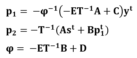
Where p1 and p2 are the parity bits (modulo 2 numbers), y is the message bits. These variables are calculated as follow [4]:
LDPC decoding
An iterative algorithm is used to decode LDPC codeword. The iterative decoding is a bit-flipping algorithm (see [1] for detailed explanations about the algorithm).
In each iteration with the bit-flipping algorithm, a syndrome vector S is calculated. In the S vector, any non-zero components correspond to unsatisfied parity check equations due to bit errors in message bit y. these bits in the y component are then flipped. This iteration is run until error bits in the message are minimised (if not eliminated).
The syndrome equation is as follow:

Where S is the syndrome equation, c is the LDPC codeword and H is parity-check matrix.
Channel coding performance comparison results
This brief comparison presents four type bit error rate (BER) performances, that are four types of message: without coding, with TURBO, convolutional and LDPC coding.
The comparisons test uses randomly generated message bits. These message bits are then flipped due to simulated noise following different channel SNR.
The effective requirement for the performance comparisons is for channel SNR to be able to transmit bit with 1ppm BER.
From figure 7 below, to be able to transmit bit with 1ppm BER, the required channel SNRs are 17dB, 11dB, 11dB and 7.5dB for transmission without coding, with LDPC, with TURBO and with convolutional code, respectively.
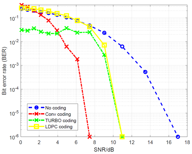
The results for TURBO and LDPC codes shown in figure 7 above are not optimal as their decoding algorithm parameters are not set to optimal values recommended in [3,4].
Theoretically, the TURBO or LDPC code could potentially has the best performance.
It is important to note that for LDPC, the computational cost for each iteration is low, but LDPC requires large iterations to have an optimal decoding performance.
Otherwise for TURBO code, TURBO code has high computational cost for each iteration but requires only few iterations to have an optimal decoding performance.
From figure 7 above, the convolutional code provides a channel SNR improvement for 1ppm BER transmission is about 10dB (from 17dB to 7.5dB). Again, the TURBO code and LDPC performances in this case are not at their optimal condition.
Conclusion
Transmitting messages or data via a noisy wireless transmission will have errors on the message (data) bits when the messages are received. This noisy channel reduces the maximum channel capacity that channel can transmit.
These bit errors cause the decoded received messages give incorrect information. To eliminate or reduce bit errors during a wireless transmission, channel coding is implemented.
Channel coding adds bit redundancy on an original message to gain ability to correct bit errors at a receiver side.
GNSS signals are one of the most suitable applications of channel coding since GNSS signals are generally weak and noisy.
There are two main channel coding types: block and convolutional codes. Examples of block code are Hamming code, CRC code and LDPC. Meanwhile, examples of convolutional codes are convolutional and TURBO codes. These channel codes have been briefly explained.
Finally, a brief comparison of convolutional, TURBO and LDPC codes performances proposed for GNSS signals are presented.
Reference
[1] Johnson, S.J., 2010. Iterative error correction: Turbo, low-density parity-check and repeat-accumulate codes. Cambridge university press.
[2] Proakis, J.G., Salehi, M., Zhou, N. and Li, X., 1994. Communication systems engineering (Vol. 2). New Jersey: Prentice Hall.
[3] https://public.ccsds.org/Pubs/131x0b4.pdf (CCSDS TURBO code)
[4] https://www.gps.gov/technical/icwg/IS-GPS-800H.pdf(NAVSTAR LDPC code)
You may find some interesting items by shopping here.
