Circular buffer for real-time applications with equal input and output data rate
In this post, we will discuss two types of real-time processing applied to global navigation satellite system (GNSS) signal processing. In addition, we will discuss a circular buffering system for real-time applications with equal data rate of input and output.

Real-time applications are very common in many engineering applications, from manufacturing, measurement, testing to signal processing.
In this post, we will discuss two types of real-time processing applied to global navigation satellite system (GNSS) signal processing. In addition, we will discuss a circular buffering system for real-time applications with equal data rate of input and output.
READ MORE: Real-time decoding of NAV messages of Septentrio receiver in C programming language
Do you want to have good research philosophies and improve your research management and productivity?
This book is a humble effort to map well-known and proven principles and rules from various disciplines, such as management, organization decision theory, leadership, strategy, finance and marketing, into a single practical research guide that applies to all disciplines.

You can also get this book from Rakuten Kobo.
Types of real-time applications
In manufacturing, measurement, testing and signal processing, real-time processing is instrumental in delivering critical functioning applications that can be used on the field.
In real-time processing, we can divide into two main categories:
- Type 1: Real-time processing where the data rate of the input and output is not-equal.
- Type 2: Real-time processing where input data rate = output data rate. In this case, all processing steps should approximately at the same processing speed so that data flows are always continuous.
Let’s discuss these two types of real-time processing as follows.
Type 1: input rate is not equal to output rate
In this type of real-time processing, very often, the processing has an input at very high data rate and then produced output in a very low data rate.
That is, commonly, the applications receive signals (can be RF signal, image data stream from an imaging sensor or measurement signals) and produces some values or parameters.
For example, in measurement, the input is a stream of 2D images and the output is the measurement of diameter of a hole
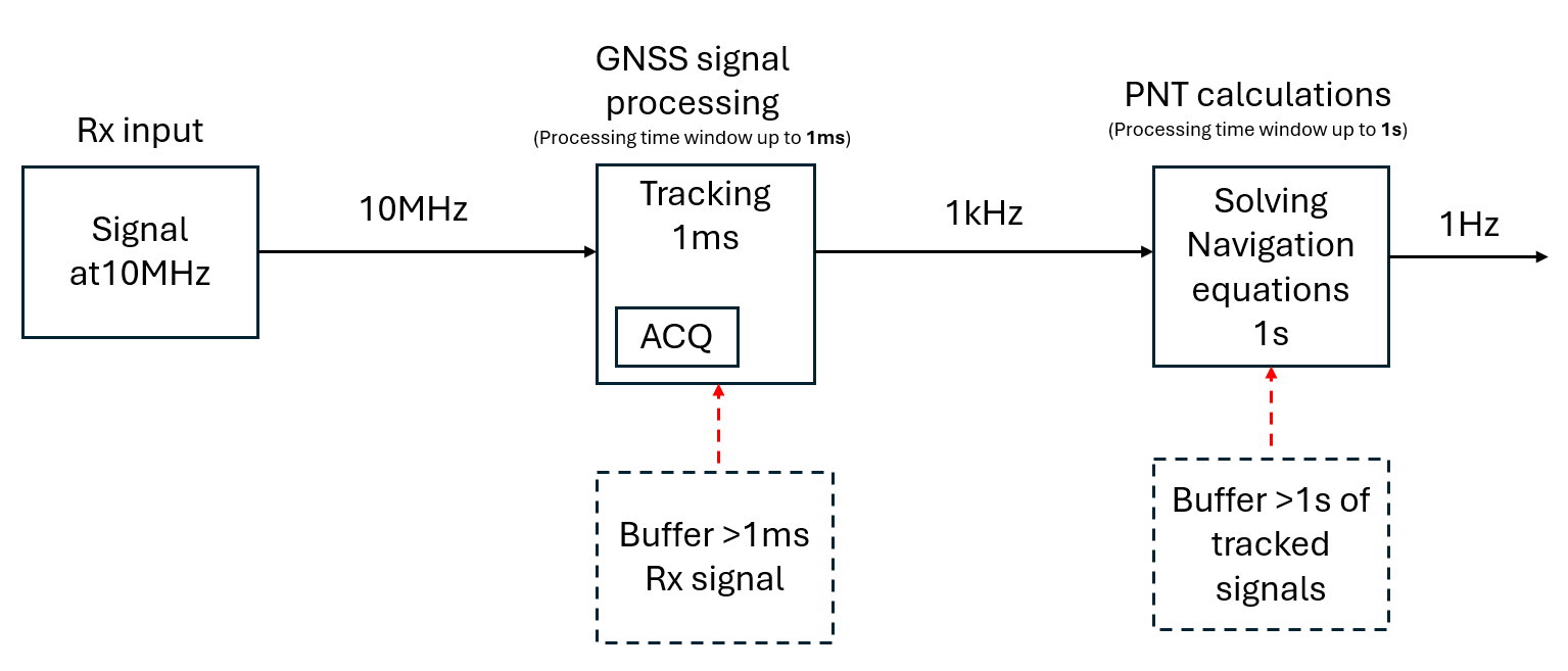
In the case of GNSS applications, the input is an RF signal sampled at high rate in MHz and the output is position solutions very often with 1Hz data output rate. Figure 1 below shows a high-level view of real-time signal processing in GNSS applications.

Detailed view of GNSS signal processing can be seen in figure 2 below. In this figure, the GNSS signal processing chain is RF signal reception, signal acquisition and tracking and then signal demodulation and position solution calculations.
In figure 2, let’s say the sampling rate is 10MHz. In GPS L1 signal, in this example, we will process the signal for the tracking with 1ms coherent integration time (since the PRN code rate is within 1ms). With this 1s coherent integration time, the output rate of the tracking process is 1kHz (the data rate is reduced from 10MHz to 1Khz).
Then, from the tracked signals with data rate of 1KHz, demodulation processes are performed, and user receiver positions are calculated. Usually, the solution is given every 1s. That is, the final output of the signal processing is 1Hz.
This type of real-time processing example has an input data rate at 10MHz and the output data rate at 1Hz. Meaning, each process steps can have a different processing speed. The position calculations have a “processing room” of 1s processing time.
Normal stacked buffers can be used to smoothen the data flow from in this type of real-time processing as shown in figure 2.

Type 2: Input rate = output rate
This type of real-time processing is typically more challenging than the type 1 real-time processing in the sense that more constraints apply to type 2 real-time processing than type 1 real-time processing.
One obvious example for the type 2 real-time processing is signal cleaner applications. In this application, we want to clean input signals (can be an RF signal, analog signal, digital signal, images) containing noises or interferences and send the cleaned signal as output signal.
Figure 3 below shows an example of type real-time processing for signal cleaner where the input and output signal are at the same 10MHz rate (sampling rate is 10Mhz). In figure 3, the processing time window to clean the signal should be less than the instrument delay.

There are conditions for this type of real-time processing to be effectively work:
- The output (e.g., Tx) and input (e.g., Rx) processing speed is equal.
Very often, this condition can be meet if the input and output sensors are at the same devices, such as a software-defined radio (SDR) devices with RF Rx and RF Tx capability.
This condition may not be applied for example, in manufacturing measurement system, where the input sensor and the output sensor can be different devices.
- The data processing speed is the same with output (e.g., Tx) and input (e.g., Rx) speed.
The data processing speed should be not longer than the Tx and Rx speed. If the processing speed is slower than the input and output rate, the data flow continuity will be broken and no buffer systems can be used to solve this situation.
Figure 4 shows and example if data processing speed > Tx processing speed. In this figure let’s assume that we captured (Rx) 1s of RF signal and transmit (Tx) 1s of the RF signal.

Let’s assume the instrument delay to between Rx-Tx chain is 5ms (we are talking in digital domain processing and not in analog and RF domain). Hence, the processing time should be < 5ms.
If the processing time is > 5ms, no matter how big the buffer we use, at some point, the buffer will be empty.
For example, let’s say our processing time of 1s data is 0.2s (200ms). Then, after 400 buffers (1s per buffer), that is at time step = 0.2s, the buffer will be empty since the Tx speed is faster than the processing speed.
- The data processing speed can be faster (not slower) than the output (e.g., Tx) and input (e.g., Rx) speed. But, there should be a condition where the data processing will wait if it reaches the Rx processing pointer.
READ MORE: The problem of writing high-digit numbers into a file and its solution
Circular buffer for real-time processing where input rate = output rate
One solution for type 2 real-time processing applications with input rate = output rate is by implementing a circular buffer.
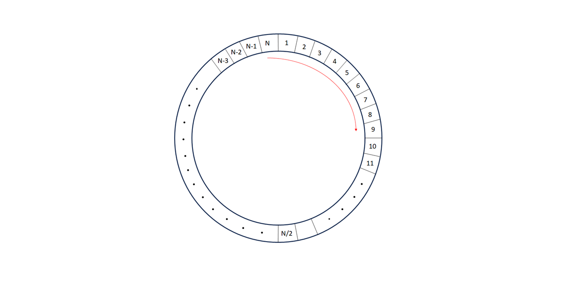
Figure 5 below shows the illustration of a type of circular buffer for application of type 2 real-time processing. In this type of circular buffer, the size of the buffer is fixed. Then, there will be three types of threads (parallel processes).
The threads will be:
- Data input (e.g., RX) thread. This thread is responsible to take input data such as RX capture at certain sampling rate.
- Data processing thread. This thread is responsible to process the input data or signal to improve the signal condition, such as cleaning noise in images or interference in RF signals.
- Data output (e.g., TX) thread. This thread is responsible to send processed data (e.g., signal) as output data at the same sampling rate of the input data.
In figure 5, the sequence of the threads should be input (e.g., RX) thread, processing thread and output (e.g. TX) thread.
Ideally all the processing time of the input, data processing and output thread should be the same ($t_{RX} = t_{processing} = t_{TX}$).

The processing time $t_{processing}$ can be faster (not slower) than the input $t_{RX}$ and output $t_{TX}$. In this case, the data processing thread should wait when the data processing thread is about to overlap (just before) the input (RX) thread.
Figure 6 shows the mechanism of the situation where the data processing thread is faster than the input (RX) and output (TX) processing threads and hence the data processing thread should wait until new data is received by the input thread.

The pseudocode of this circular buffer implementation is as follows:
#include <stdio.h>
#include <pthread.h>

pthread_mutex_t mutex;
pthread_cond_t cond;

void *thread_INPUT(void *ptr_msg){

    //read input data for sometime to fill buffer

    while(true){

        pthread_mutex_lock(&mutex);

        //read input data

        pthread_cond_signal(&cond,&mutex);

        pthread_mutex_lock(&mutex);

    }

}

void *thread_PROCESSING(void *ptr_msg){

    while(true){

        if(/*the_buffer_has_been_filled*/){

            pthread_mutex_lock(&mutex);

            //process input data

            if(/*no_data_to_process*/){
                pthread_cond_wait(&cond,&mutex);
            }

            pthread_mutex_lock(&mutex);

        }

    }

}

void *thread_OUTPUT(void *ptr_msg){

    while(true){
        if(/*enough_data_has_been_processed*/){
            //send the processed data
         }
    }
}

int main(){

    int retVal;
    char *msg;

   //Init mutex and condition variable
    pthread_mutex_init(&mutex,0);
    pthread_cond_init(&cond,0);

    //Initializing threads
    pthread_t t_INPUT;
    pthread_t t_PROCESSING;
    pthread_t t_OUTPUT;

    //calling threads
    msg="thread_INPUT";
    retVal = pthread_create(&t_INPUT, NULL, thread_INPUT, (void *)msg);

    msg="thread_PROCESSING";
    retVal = pthread_create(&t_PROCESSING, NULL, thread_PROCESSING, (void *)msg);

    msg="thread_OUTPUT";
    retVal = pthread_create(&t_OUTPUT, NULL, thread_OUTPUT, (void *)msg);

    //Threads join
    pthread_join(t_INPUT,NULL);
    pthread_join(t_PROCESSING,NULL);
    pthread_join(t_OUTPUT,NULL);

}
READ MORE: TUTORIAL: MATLAB software inter-connection and cooperation with PYTHON software using pyenv()
Conclusion
In this post, we have discussed two main types of real-time applications that are real-time applications with input rate Is not equal to output rate and real-time applications with input rate = output rate.
When the data rate of input and output are the same, real-time applications becomes more challenging. Because all aspects of processing stage should be approximately at the same speed to keep data flow continuities.
A circular buffer system and the main procedure to create real-time applications with data rate of input and output are the same has been presented.
The application of this application for GNSS signal processing has also been discussed. This method has a huge potential for real-time “signal interference cleaning” processing or other applications.
You may find some interesting items by shopping here.
