General procedures to operate a tactile coordinate measuring machine (tactile-CMM)
There is a general procedure to operate a tactile coordinate measuring machine (tactile-CMM). In this post, we will discuss this general procedure that can be implemented to all types of tactile-CMM from various manufacturers.

There is a general procedure to operate a tactile coordinate measuring machine (tactile-CMM). In this post, we will discuss this general procedure that can be implemented to all types of tactile-CMM from various manufacturers.
Tactile CMM was invented due to the need to automate the verification of geometric tolerancing (GD&T). before the invention of tactile-CMM, the verification of GD&T requires a long time and complex setup. This complex procedure causes only a specially trained operator can perform GD&T verifications before the tactile-CMM was invented.
To correctly and efficiently operate a tactile-CMM, a certain knowledge should be learnt by any users. For example, the user should understand the concept of alignment and coordinate system. Only by understanding of these exampled concepts, the user can correctly perform geometrical and dimensional measurements by using any tactile-CMM.
Note that the procedure explained and discussed in this post is for tactile-CMM with computer-numerically controlled (CNC). That is, the tactile CMM can be run automatically.
(Note: All 3D illustrations were created by using a CATIA 3D modelling software)
Let us discuss the procedure!
READ MORE: Tactile CMM: The reference of dimensional and geometrical measuring machine in industry.
Overview of the general procedure to operate a tactile-CMM
For tactile-CMM, points on the surface of a measured part are collected individually one-by-one, either by scanning or point-to-point detection.
It is a different case for optical CMM. For Optical-CMM, the points on the surface are obtained collectively to get a set of points (point clouds) in one acquisition cycle. The point clouds are then analyses to separate between good and bad (outlier) points.
Back to tactile-CMM, there exist a general procedure to operate tactile-CMM. Although, there might be slight differences due to specific procedures are added for each type of tactile-CMM according to its manufacturer or due to specific addition by a specific measurement laboratory.
Figure 1 below shows the schematic view of the general procedure to operate a tactile-CMM for dimensional and geometrical measurements.
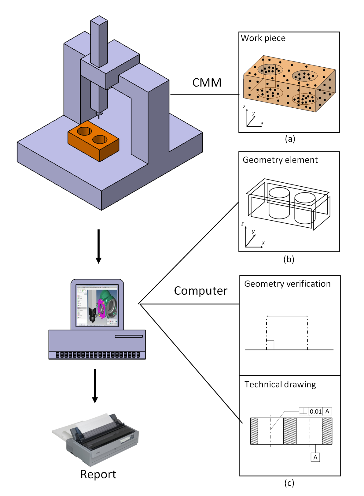
In figure 1, the general procedure to operate a tactile CMM (equipped with CNC system) for dimensional and geometrical measurements are divided into three main processes as follows:
- Detection of points on the surface of measured parts according to a pre-determined measurement plan. This process is performed by a CMM, either automatically or manually by an operator.
- Mathematical association of detected points on the measured surface to a desired nominal geometry, for example, a plane, circle or sphere. That is, the process is called mathematical geometrical fitting process. This process is performed by a computer connected to the CMM.
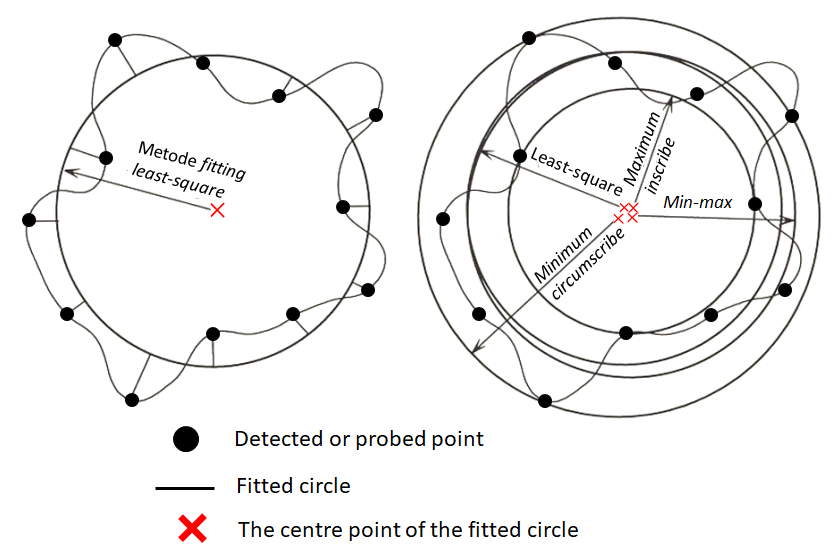
Figure 2 below shows an example of point association or fitting process of points from a measured surface to a circle geometrical element. In figure 2, it can be observed that with the use of different fitting methods, the obtained circle parameters: radius and centre point location, are also different.
A correct fitting method should be used depending on the types of geometrical verification and the types of design functionality of a measured part.
3. Geometrical verification by calculating the dimension and geometry that are wanted to be verified from a measured part. The calculation results are compared to the 2D technical drawing of the part. After this step, the report of the measurement process can be made. This process is also performed by the computer connected to a tactile-CMM.
Measurement planning creations or preparations, geometrical fitting processes and geometrical verifications are performed by a special software that specifically connected and control a tactile-CMM used for measurement.
Examples of such software are Calypso for Zeiss CMM, Quindos for Leitz CMM and PC-Demis for DEA and other CMMs.
Specifically, for CMM operation, the operation can be divided into:
1. Measurement preparation
The preparation processes that need to be considered before operating a tactile-CMM are the conditioning of the CMM, checking a technical drawing and verifying of a measured part, selecting a stylus and probe to be used, making a measurement report and providing measurement safety.
2. Measurement program creation
Measurement program is divided into stylus qualification, alignment process, inspection, analysis, report, measurement program test and revision and improvement of the measurement program.
Let us discuss these two operations as follow:
Tactile-CMM measurement preparation
Before using a tactile-CMM, the CMM should be conditioned to be in its best operational condition. Dust attached to the CMM should be cleaned beforehand. Especially, dust on the surface for air bearings should be cleaned with a special procedure.
A CMM with air bearings, the supply of compressed air should be assured to be at the specification from the manufacturer of the CMM. The stylus, probe and reference sphere should be cleaned from dust as dust will significantly affect the CMM accuracy at micrometre level. Alcohol is a common chemical to be used for cleaning.
Before using the CMM, the CMM should be positioned at its home position. The CMM positioning at its home position is important. Because the measurement scale of the CMM is incremental from its home position. In addition, to be able to correctly apply a volumetric error map of the CMM for error correction, the CMM should be started from its home position before any use.
The technical drawing of a measured part should be carefully checked to understand what type of measurements we need to carry on, such as flatness or perpendicularity or orientation or runout or other measurements. In addition, from the technical drawing, we can derive the most effective and efficient measurement program to make for the measurement type at hand.
A good CMM program is the program that can correctly translate the GD&T requirements to verify into a specific CMM program at hand.
The CMM program should consider:
- What datums need to be measured to perform the required geometrical measurements?
- Whether the measurement will be carried out with one or multiple types of measurement setup?
- What groups of features that need to be measured?
- How to estimate the uncertainty for the geometrical measurement result?
The selection of stylus and probe to use depends on the type of features on a measured part.
For stylus, the first thing to consider is the ability of the stylus to access the surface that wants to be measured.
For probe, its selection depends on whether the measurement requires a scanning mode and/or requires an adaptive touching force to the measured surface or not.
The principle is that, using only one stylus to measure all required measurements will be better than to use more than one stylus. Because, when using multiple or more than one stylus for measurement, the uncertainty of the measurement will increase due to an additional contributing uncertainty factor from the stylus changing mechanism.
Sometimes, by changing the orientation of a measured part slightly will increase a stylus accessibility and reduce the requirement to use multiple types of styluses for the given measurement. In addition, there is a “star” configuration for stylus so that the stylus has high accessibility to a measured surface with various shape.
Fixtures required for CMM measurement do not need to hold high forces like those required for machining process, such as milling and turning. Fixturing forces to hold a measured part should not be excessive so that deformations will not occur on a measured part. In addition, the number of fixtures should be minimal because fixtures will increase a setup complexity and may reduce the stylus accessibility to a measured surface. A small tip to hold a small part is by using a super glue.
Preparing the report from a CMM measurement is also important. The report is divided into two types:
- Report to documenting measurement processes
- Report to present measurement results
The safety of CMM operation is very important like the safety to use a production machine. The safety is mainly for operator and CMM itself. An operator should make sure that there are no parts on a CMM table that can move or shifted during the CMM operation. These parts maybe heavy and can cause injury to the operator when falling. Also, these parts may cause collision with the CMM stylus or axis that may damage the CMM.
The bearing surface of a CMM should also be assured so that the surface is not scratched due to friction with parts. Finally, the emergency stop should always be placed close to the operator reach.

Measurement program for tactile-CMM
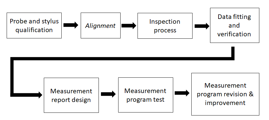
The steps of making a CMM program is presented in figure 3 below. The steps are as follows: Probe and stylus qualification, alignment, inspection process, data analysis (mathematical fitting and verification), design a measurement result report, CMM program testing and validation, revision and improvement of the CMM program.
CMM program is also called as CMM measurement planning. ASME B89.7.2-1999 [1] provides a good guide on how to make a CMM program or CMM measurement planning for dimensional and geometrical measurements.
The explanations for each step of making a CMM program are:
1. Probe and stylus qualification
The probe and stylus qualification are processes to precisely know the actual effective diameter of a stylus tip and to precisely know the orientation and length of the stylus.
Most CMM commercial software call this process as probe and/or stylus calibration. Actually, this calibration naming is not exactly correct!
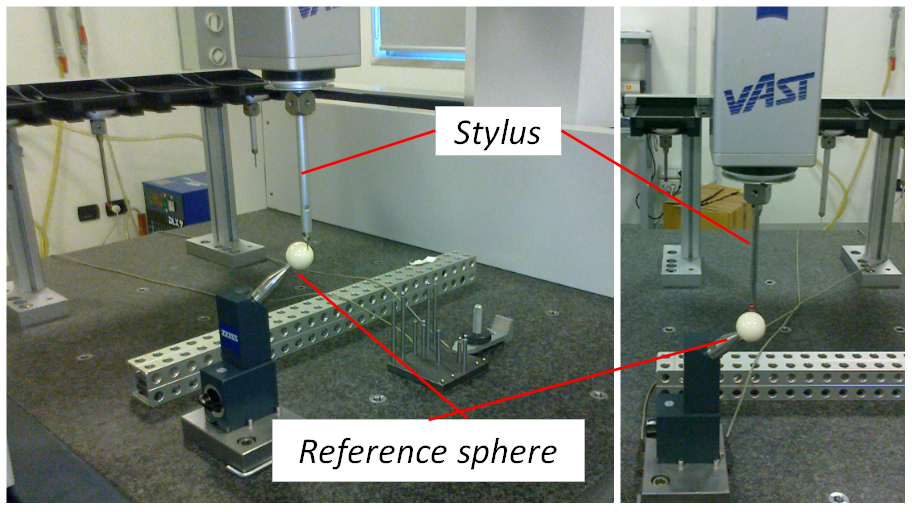
Figure 4 below shows an example of probe and stylus qualification processes. Form figure 4, the qualification processes require three elements: a reference sphere with calibrated dimension (diameter), reference stylus with calibrated diameter of its tips and its stem length, and the stylus to be qualified that will be used for measurement.
Two main steps of the qualification processes are:
- The measurement of absolute position of the reference sphere using the reference stylus
- The measurement of the reference sphere using the stylus to be qualified that will be used for measurement. This process commonly takes 25 points on the reference sphere surface. Then, with a numerical calculation process, the orientation and length of the stylus and the tip diameter can be obtained.
If there are multiple stylus in one probe that will be used in a measurement, we need to qualify all the probes and stylus within the same qualification process (the same reference sphere, place, time and operator). By using this approach, we can reduce uncertainty contributions for the probe and stylus qualification processes.
2. Alignment
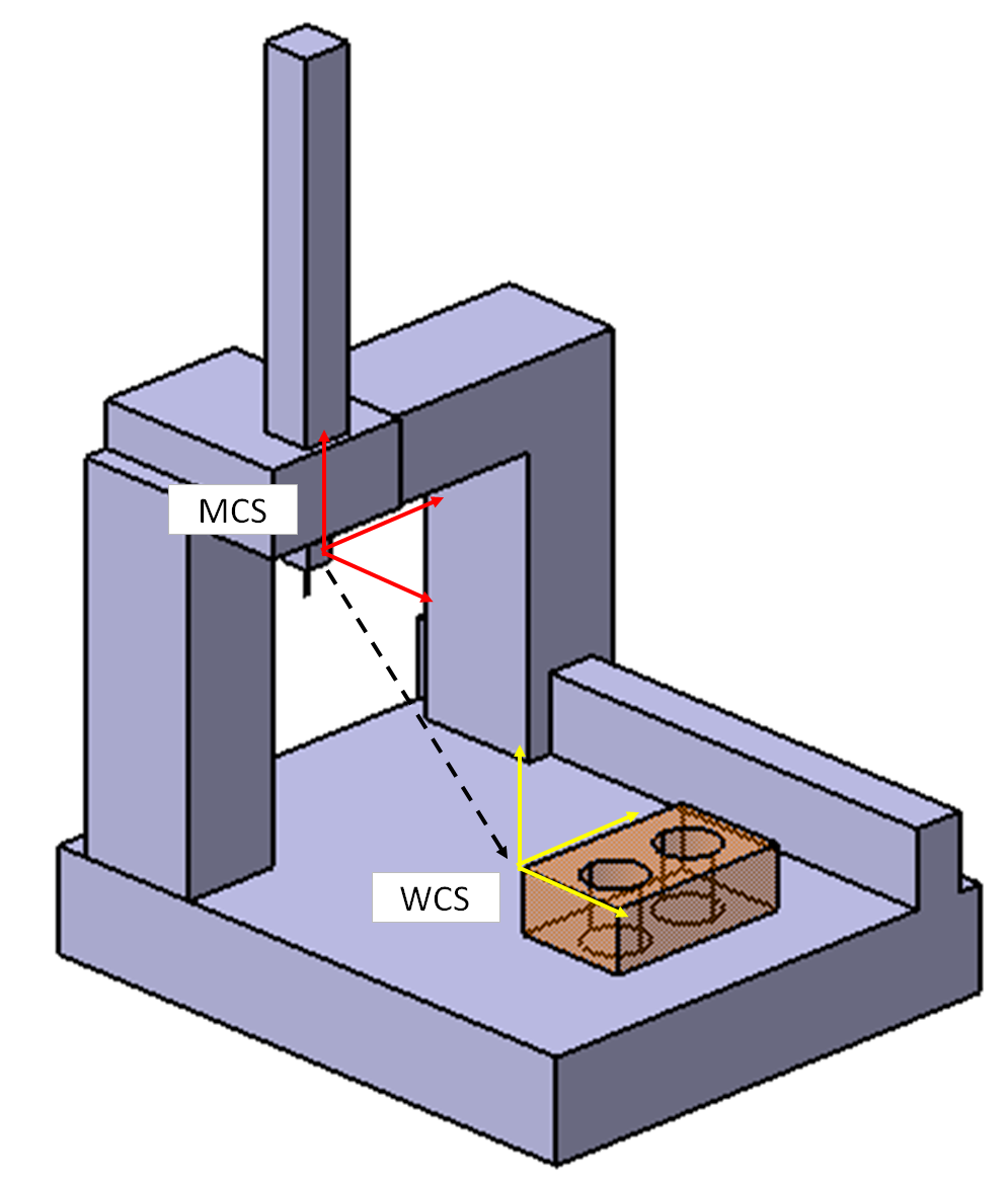
Alignment process is a process to transform the measurement coordinate system from the absolute coordinate system or machine coordinate system (MCS) of a CMM to part/workpiece coordinate system (WCS).
MCS is an absolute coordinate system that is fixed for each CMM machine. MCS has been defined when a CMM was constructed at a factory.
Figure 5 below shows the transformation from the MCS of a CMM to WCS. To determine the centre of WCS, several features (usually three planes with different orientation on a part) are probed to collect points. Then, with a numerical calculation, the centre of WCS can be determined.
The alignment in general is divided into two steps:
- Manual detection of points of the surface of features on a measured part. For a tactile-CMM with CNC system, those points are recorded into the CMM controller memory. This process is called “coarse alignment”, that is an initial alignment that is not yet precise.
- Automated detection of the points that are manually obtained before. This process is called “fine or precise alignment”. Because, when the points are obtained automatically, the motion of the CMM can be constantly controlled so that the points obtained will have a higher accuracy than points obtained manually before.
3. Inspection process
This process is to determine the strategy of measurements, for example, the measurement of position of a cylinder with respect to a datum.
In general, the design of a measurement strategy is decided to measure features that are close to each other. The aim is to reduce the distance of CMM axis travelling, so that the dynamic effect of the CMM can be reduced as well as the measurement time can also be shortened.
In this process, all related features that are required to produce the result of dimensional and geometrical measurements should be correctly defined.
Finally, the collection or detection of points on the surface of a measured part, that is sampling strategy, is also defined in this process, either by using point-to-point detection or point scanning.
4. Data analysis (fitting and verification)
This step is to process data, in term of spatial coordinate points on a surface, from measurements. In this process, a complex numerical calculation to associate points to a nominal geometrical element, such as circle, cylinder, plane and sphere. This process is the point fitting.
From this process, the reconstructed geometrical element, dimensional (such as length and diameter) and geometrical (such as position, perpendiculatiry and run-out) measurements can be derived and the results can be compared or verified with the number written in an associated technical drawing.
In general, the software of a commercial CMM provide the ability of an operator to select which what type of geometrical fitting to use, such as least-square fitting or minimum-zone fitting.
5. Measurement report design
This process is to determine the type of format of the report of a measurement to show. The report from a measurement result can be designed from a simple form such as text (for example the diameter of a cylinder) to a very complex report with various graphs.
In general, in industry the volume of measurement reports is large. Hence, the automation of producing measurement reports with a specific format is very important and required.
6. Measurement program test
After a CMM program has been made, then, the next step is to test whether the program can run correctly and give desired measurement results.
The most important thing that should be paid attention is that to make sure that there is no collision between CMM axes and a part of fixture during a complete automated measurement process.
In addition, the motion speed of the CMM axis can also be observed whether the speed is too slow or too fast. Initially, for the initial test, the motion speed of the CMM is set to be slow (can be usually set from the CMM’s joystick).
7. Revision and improvement of the measurement program
After a CMM program was made and tested and gave desired measurement results, the CMM program can be used repetitively.
Similar to making a computer program, after a program was made, always there are aspects of the program that can be revised and improved. The main goal of the improvement is to be able to speed up measurement processes.
To get or perform the same measurement type, there are many possible ways to program a CMM. Each different program performs the same measurement. Hence, a CMM program should be periodically revisited. All CMM program made should be documented in detailed step-by-step to ease future improvements.
Conclusion
In this post, the general procedure to operate tactile-CMMis presented. The procedure is applicable to all tactile-CMMs from different manufactures. This article is very useful for those who wants to operate a tactile-CMM.
The general steps to operate tactile-CMM are measurement preparation and measurement program creation.
Measurement program creation consists of probe and stylus qualification, alignment of coordinate system, inspection process, data analysis (fitting and verification), design of measurement report, measurement program test and measurement program revision and improvement.
When we understand the concept of this general procedure, using any types of tactile-CMM with various configuration can be easy.
Note that, since tactile-CMM is highly related to GD&T, then in the making of CMM program, we need to have understanding of GD&T.
References
[1] ASME B89.7.2, 1999, “Dimensional measurement planning”, ANSI, USA
You may find some interesting items by shopping here.