Geometric dimensioning and tolerancing: How to consider manufacturing processes when specifying GD&T tolerances
In this post, we will discuss why we need to consider manufacturing processes when selecting symbols of geometrical dimensioning and tolerancing (GD&T) and assigning values of each GD&T symbol on a mechanical drawing.
In this post, we will discuss why we need to consider manufacturing processes when selecting symbols of geometrical dimensioning and tolerancing (GD&T) and assigning values of each GD&T symbol on a mechanical drawing.
As has been discussed in the previous post, GD&T is not another symbol instead is a “technical language” used by mechanical design engineers to convey their design intents or encode their design messages to manufacturing and inspection engineers [1].
In this case, with GD&T, a mechanical design engineer can convey their intent on how their parts should be made with certain machining processes and strategies as well as how the parts should be verified (with what measuring instruments and measurement strategies to use) [2].
Hence, a mechanical designer should also consider manufacturing processes in their GD&T specification processes.
GD&T complements the traditional “+/-” tolerancing and to remove ambiguities on the meaning of tolerances specified in the mechanical drawing of a part or assembly.
There are five basic groups of GD&T tolerances, that are form, orientation, location, profile and runout tolerances. These five basic GD&T groups are based on ASME Y14.5 standard (and ISO 1101-Geometrical product specifications for the European standard counterparts).
After reading this article, readers will be able to understand important aspects to consider related to part manufacturing processes when specifying GD&T tolerances on the part features.
Do you want to have good research philosophies and improve your research management and productivity?
This book is a humble effort to map well-known and proven principles and rules from various disciplines, such as management, organization decision theory, leadership, strategy, finance and marketing, into a single practical research guide that applies to all disciplines.

You can also get this book from Rakuten Kobo.
Things to consider with respect to manufacturing processes when we specify GD&T
GD&T and manufacturing processes of a part are tightly coupled. They should be considered together and not independently!
A mechanical engineer should consider how their part will be manufactured, what materials the part should be made of and what manufacturing process to be used as well as what strategies to be applied.
The designer should consider whether their manufacturing machines are capable of making their parts satisfying their tolerances or not. If not, they should consider where they will subcontract the manufacturing processes to make their parts.
These considerations directly affect the total product cost.
Things to consider related to manufacturing processes when specifying GD&T tolerances are as follows (only several mentioned here, but there are of course a lot more examples in real GD&T applications and part manufacturing):
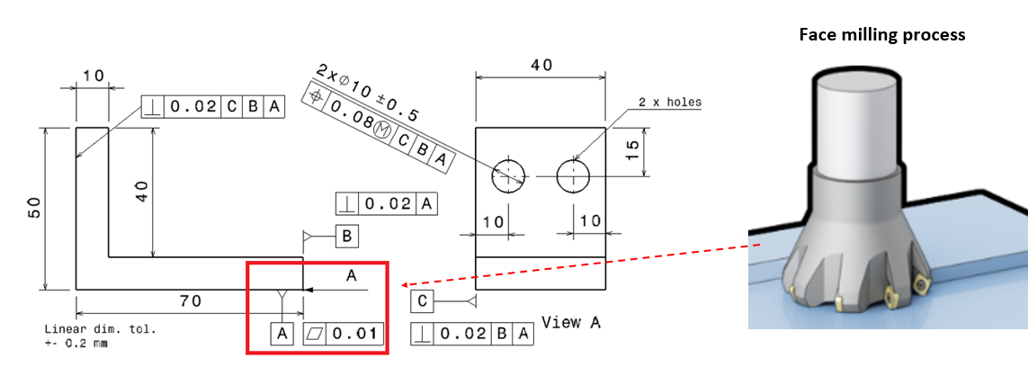
Consider our face milling process precision
One of the most common tolerances is flatness tolerance. Especially, this is a favourite tolerance for the large surface of a part that defines the base of the part.
Also, this tolerance usually assigned as Datum A as the main reference of all GD&T tolerances assigned to the part.
Since the tolerance is as Datum A, the flatness should have a very tight tolerance. Because any variations in this flatness feature, error will be propagated and amplified throughout the whole tolerance chain on the part and then on the assembly containing the part!
That is, we need to consider whether our machine tool can provide face milling processes within the flatness accuracy that we have given to the part.
Figure 1 below shows the illustration of the flatness operation and tolerance. In this figure, the flatness tolerance is set to be 0.01mm. Hence, we need to understand that our face milling process should have accuracy of higher than 0.01mm.
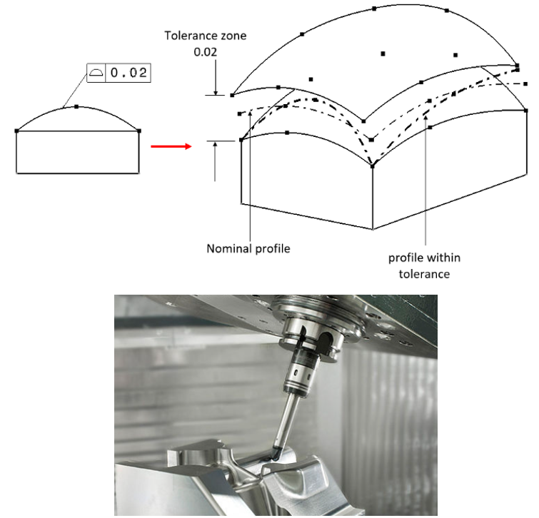
Consider our machine tools configurations (3-axis or 5-axis)
With 3-axis machine tools, we mostly can only manufacture prismatic parts. We still can try to process free-form surfaces (non-planar features), but with 3-axis machine tools, we only get free-form geometries with rough surfaces.
Meanwhile, with 5-axis machining, since we have two additional rotational axes, we can position our tools exactly opposite to the normal vector at any point on the free-form surface.
Hence, we can manufacture a smooth free-form surface with 5-axis machine tools.
We need to consider our machine tool configurations that we have when we specify surface profile tolerances.
Figure 2 below shows the relation between surface profile tolerances and the requirements to have 5-axis machine tool configurations.
To satisfy surface profile tolerances, we need a smooth free-form surface that can be manufactured by 5-axis machine tools instead of 3-axis machine tools.
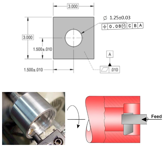
Consider our finishing process such as boring process
In position and diameter tolerances, sometimes we put symbol of least-material condition (LMC) assigned to a hole feature as show in figure 3 below.
With LMC on a hole feature, it means that when the hole is made smaller than its nominal diameter, in this case 1.22mm (figure 3), we have bonus tolerance on the positions for about 0.03mm (1.25-1.22) mm.
LMC is usually used since we want to leave a little bit of material for finishing process. In this case shown in figure 3, we want to apply a boring (hole diameter enlargement) process to a drilled hole to have a very smooth surface and/or precise hole diameter.
Hence, if the hole is drilled 1.22mm, it means that we still have 0.03 excess material that we can still remove for the boring process.
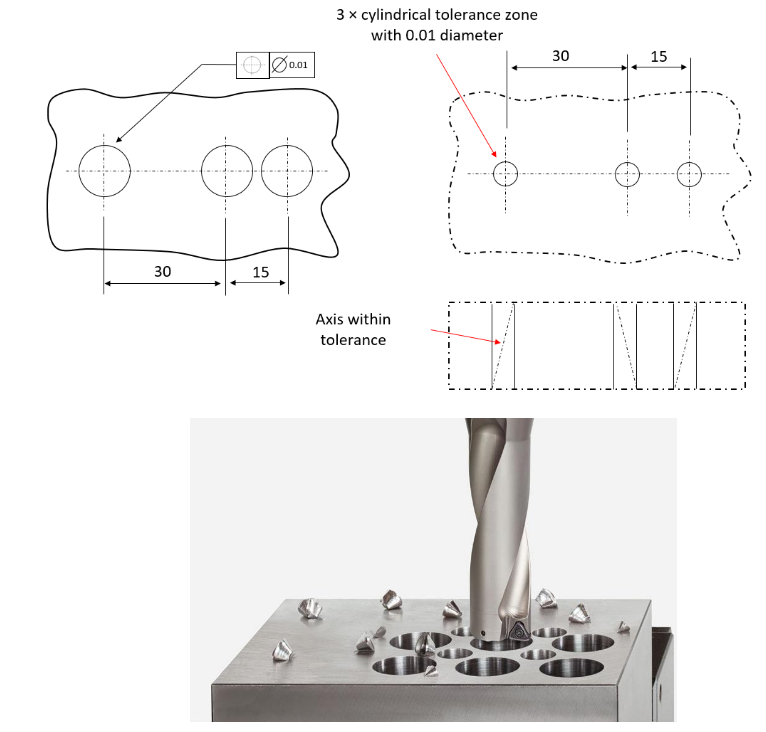
Consider our milling machine positioning accuracy
Still related to position tolerances, when assigning the position tolerance of holes in a part for drilling, we need to consider how accurate our machine tools positioning (related to machine tool axis) and drilling (related to tools and machining process) accuracy is.
In figure 4, we can see we assign 0.01mm position tolerance for the hole. It means our machine tool positioning accuracy combined with our drilling process should be < 0.01mm.
Otherwise, we cannot achieve our positional tolerance applied on the holes of the part.
From this description, we can see how positional tolerances are tightly related to machine tool-axis accuracy!
The advantages of considering manufacturing processes at GD&T specification stage are many, some of them are we can use GD&T and process analysis to:
- Revising mechanical designs to match our manufacturing capabilities with very minimal cost and time.
- Predicting manufacturing costs so that we can revise our mechanical design and manufacturing process/strategies at early stage.
- Supporting strategic decisions whether to outsource manufacturing processes to other companies or not.
- And many more.
READ MORE: 2D tolerance stack-up analysis with examples
Conclusion
In this post, we have discussed the relation of GD&T with respect to manufacturing processes of parts.
Mechanical design engineers should have some knowledge about manufacturing processes.
Hence, when they specify their GD&T tolerances on parts, they are aware of what manufacturing capabilities their workshop have and whether their manufacturing processes can make their product according to their tolerances.
Considering manufacturing processes at the GD&T specification stage have immense benefits, for example, revising design to match our manufacturing capabilities with very minimal cost and time, predicting manufacturing costs and supporting strategic decisions whether to outsource manufacturing processes to other companies or not.
References
[2] Syam, W.P., 2018. Metrologi manufaktur: Pengukuran geometri dan analisis ketidakpastian.
You may find some interesting items by shopping here.