GNSS signal tracking: The need for both PLL and DLL tracking
In this post, we briefly show what PLL and DLL are, why they need to be both implemented and the effect when we only use either PLL or DLL tracking loops.
The most common GNSS signal processing involves both phase-locked loop (PLL) and delay-locked loop (DLL) processes.
In this post, we briefly show what PLL and DLL are, why they need to be both implemented and the effect when we only use either PLL or DLL tracking loops.
A phase-locked loop (PLL) is a control system for generating a matched-phase output signal with respect to an input signal. The PLL loop tracks the Doppler frequency offset of a GNSS signal.
A delay-locked loop (DLL) is a control system for tracking the code delay of a GNSS signal during a tracking process.
Detailed formula derivations and discussions about PLL and DLL tracking loops can be found in [1,2].
Let’s go into the brief discussion.
READ MORE: Brief discussions on uncertainty contributors of GNSS-based positioning (Part 4)

Signal tracking: The combination of PLL and DLL tracking
The basics of GNSS signal tracking contain both PLL and DLL tracking loops used to track the Doppler offset and code delay, respectively.
The Doppler offset and code delay change overtime because the GNSS satellites are always moving although a receiver that records the GNSS signals is static.
Figure 1 below shows the diagram of the basic DLL+PLL tracking loops. The DLL and PLL tracking loops work together for each tracking epoch.
In figure 1, the DLL loop uses I (in-phase) and Q (quadrature) early and late correlation outputs without using the IQ prompt correlator. Meanwhile, the PLL loop only uses the I and Q prompt correlation outputs.
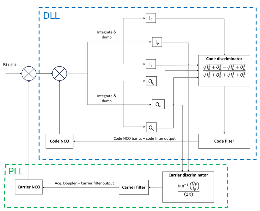
The DLL loop tracks the peak of the signal correlation output (the prompt correlation) calculated from a GNSS signal and its local PRN replicas. This loop consists of a DLL discriminator and a DLL loop filter used to smooth the discriminator output.
In figure 1, the code discriminator for the implemented tracking is normalised “early-minus-late power”. This discriminator is formulated as follow:
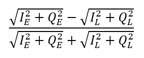
The advantages of this code discriminator are [1,2]:
- This discriminator is robust for processing noisy signals.
- This discriminator uses both the in-phase and the quadrature arm (both I and Q channels) so that it is independent to the performance of the PLL tracking.
- This discriminator is normalised so that it can be used for signals with different carrier-to-noise ratio and different signal strength.
One of the drawbacks of this code discriminator is that it has high computational cost (but in the implementation, the computational cost is negligible with respect to current computing power) compared to other code discriminators.
The output of this code discriminator then goes into a DLL loop filter. The output of the loop filter is used to determine the actual code rate.
From figure 1, the actual code rate (Code NCO) at a tracking epoch is determined by subtracting the basic code rate (Code NCO basics), for example for GPS L1 the basic code rate is 1.023Mcps, with the code filter output.
There are many other code discriminators that can be used for different code-delay tracking (DLL) performance, for example, non-normalised early-minus-late power, dot-product power, dot product and others [1,2].
Meanwhile, the PLL tracking loop, used for tracking Doppler frequency offsets due to movement from either/both a receiver and GNSS satellites, use a common carrier discriminator.
The carrier PLL discriminator for the implemented tracking loop is formulated as follow:
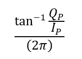
Basically, the carrier discriminator, in an ideal condition, all the energy will be at the in-phase arm so that the discriminator (the Doppler offset change) is zero.
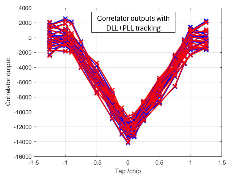
Figure 2 below shows the correlator outputs for in-phase signal when the signal tracking uses both DLL and PLL loops.
In figure 2, the plot shows correlator outputs for 20ms period with 1ms coherent integration time. That is, there are around 20 correlator outputs in the plot.
The results of the signal tracking using both DLL and PLL tracking show the Doppler frequency offset can be removed from the signal and the PRN code can be tracked.
READ MORE: Real-time decoding of NAV messages of Septentrio receiver in C programming language
The effect of only using DLL tracking
In this section, we will observe the effect of only using a DLL tracking loop in GNSS signal processing.
Figure 3 below shows the schematic view of DLL only tracking loop. As can be seen from this figure, without the PLL and with the type of code discriminator, the tracking does not require prompt correlator outputs at both In-phase and Quadrature signals.
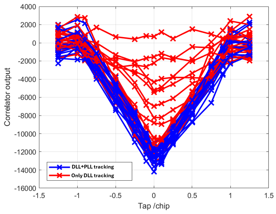
The correlation deteriorating effects of only implementing DLL tracking is shown in figure 4 below.
From figure 4, we can see that after some time the power of correlation outputs reduces to near zero. The reason is that since we do not track the Doppler offset (by performing a PLL tracking loop), we cannot remove the Doppler offset in the signal.
Overtime (depending on the dynamic of the receiver and environmental noises), due to this Doppler frequency offset, the PRN code signal power (energy) on the in-phase arm (channel) leaks into the quadrature arm.
Hence, the correlation calculations between the signal and PRN local replica cannot produce any auto-correlation power. That is, the correlator shape cannot be faithfully calculated.
In this situation, we can say that the tracking has been lost.
READ MORE: Correlator outputs for clean and spoofed GPS L1 C/A signals
The effect of only using PLL tracking
In this section, we will observe the effect of only using PLL tracking in GNSS signal processing.
Figure 5 below shows that the PLL-only tracking loop implementation is the simplest tracking process for GNSS signal processing. Because the PLL tracking (with the simplest carrier discriminator) only uses in-phase (I) and quadrature (Q) prompt correlator outputs.
Unlike in the case of DLL tracking, PLL tracking (with this simplest discriminator) does not utilise any correlator outputs other than the prompt outputs. Hence, basically it only needs calculation of two correlator outputs at prompt tap delay.
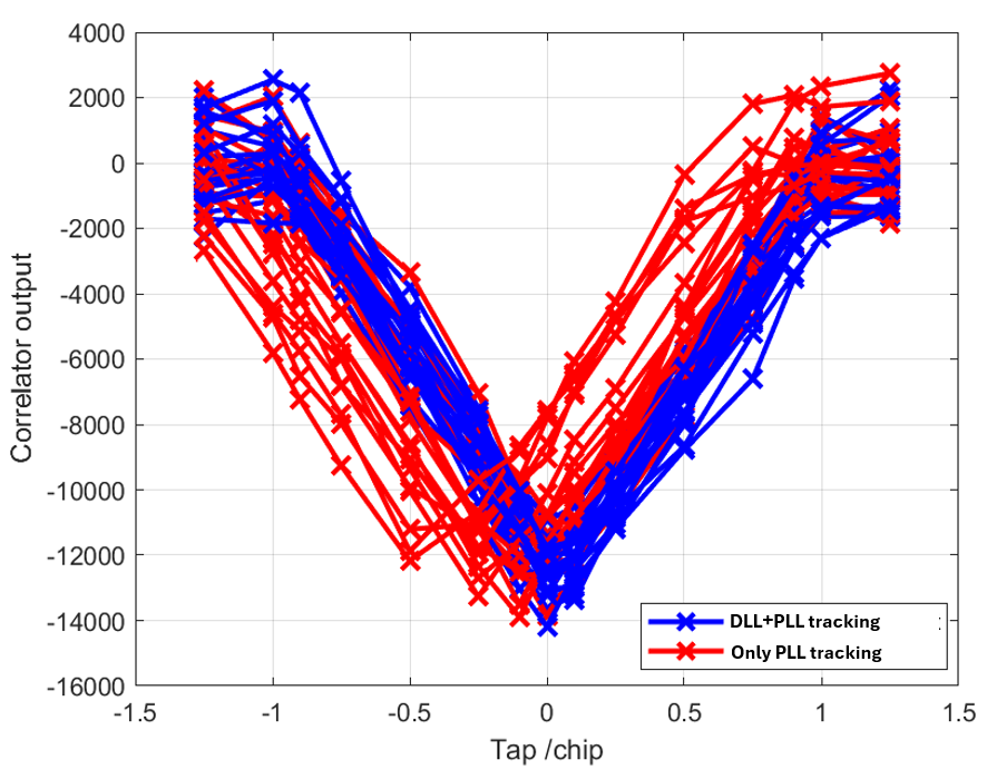
Similar to the case of DLL-only tracking, in PLL-only tracking, after some time, there will be a significant correlator outputs degradation.
Figure 6 below shows for the case of PLL-only tracking, after some time (depending on the dynamics of the receiver and environment noise) the prompt correlator outputs will systematically shift gradually over time.
When the estimated prompt tap shift achieves >1chip delay, the DLL loop will lose track of the code delay and hence lost the overall signal tracking process.
From this discussion, we can see that both DLL and PLL tracking are required to be able to faithfully reconstruct the correlator output and then constantly track GNSS signals.
READ MORE: The problem of writing high-digit numbers into a file and its solution
Types of GNSS signal processing and where PLL and DLL are relevant
There are several types of GNSS signal processing. For now, there are at least three types of GNSS signal processing. Two of them involve signal tracking processes and another one does not used any tracking processes at all [3].
These three types of processing are [3]: GNSS signal processing with standard tracking loop, GNSS signal processing with vector tracking loop and GNSS signal processing without any tracking.
GNSS signal processing with standard tracking loop
This type of GNSS signal processing the most typical one. It contains sequential processing from signal acquisition, tracking and then PVT calculations.
This processing type assume that the signal received from the same user’s position and velocity and there is no feedback from user’s position and velocity. This processing also covers in case for users are dynamics within a certain limit.
Figure 7 below shows the schematic view of this standard GNSS signal processing.
GNSS signal processing with vector tracking loop
This GNSS signal processing has the same basis operation with the previous mentioned typical GNSS signal processing.
However, this signal processing utilises feedback from users. That is, the code delay (DLL tracking loop) and Doppler frequency (PLL tracking loop) are the function of user’s positions and velocities.
This feedback can be obtained by using an inertial measurement unit (IMU) sensor or from other sources.
Very common, Kalman filter derived methods are used to incorporate this feedback into DLL and PLL tracking loops.
Figure 8 shows the schematic view of this type of GNSS signal processing with vector tracking loop.
GNSS signal processing without any tracking
The latest development of GNSS signal processing is by direct position estimation [4].
In this GNSS signal processing, there are no delay and Doppler frequency offset tracking processes involved. Instead, coarse PNT solutions are estimated from sampled data, e.g., acquisition search spaces, and then track the user’s positions directly.
Conclusion
In this post, we briefly discuss the role of both DLL and PLL tracking loops in conventional and well-established GNSS signal processing.
In addition, the effect of only using either DLL or PLL tracking on tracked signals have also been discussed.
Finally, a novel direct position estimation method to estimate user’s positions from GNSS signals, without performing DLL and PLL tracking loops, has been mentioned as well.
Reference
[1] Kaplan, E.D. and Hegarty, C. eds., 2017. Understanding GPS/GNSS: principles and applications. Artech house.
[2] P. Misra and P. Enge. 2006. “Global Positioning System: Signals, Measurement and Performance.” 2nd edition.
[3] Borio, D. 2023. Navisp Industry Days 2023. ESA/ESTEC, Netherlands.
[4] Closas, P. and Gusi-Amigo, A., 2017. Direct position estimation of GNSS receivers: Analyzing main results, architectures, enhancements, and challenges. IEEE Signal Processing Magazine, 34(5), pp.72-84.
You may find some interesting items by shopping here.
