Manufacturing and space: Multilateration using ranging signals for large scale dimensional metrology
Multilateration is a position determination method that is locating an object by accurately computing the distance between the object and three or more other objects (e.g., transmitter or laser tracker) with known positions. This method is also known as hyperbolic position determination.
Multilateration is a position determination method that is locating an object by accurately computing the distance between the object and three or more other objects (e.g., transmitter or laser tracker) with known positions. This method is also known as hyperbolic position determination.
This multilateration method is an established method for position determination in global navigation satellite system (GNSS), such as GPS, and in large-scale dimensional measurement by using laser tracker systems.
In this post, we will discuss the intersection between GNSS and manufacturing metrology via the discussion of multilateration method.
In addition, we will also propose and discuss potential new method that combines the advantages of multilateration implementation in GNSS and laser tracker systems for long-distance dimensional measurement that has many important applications in indoor large-scale manufacturing processes.
We will see that science and engineering methods in one field may also be applicable to other fields.
READ MORE: Manufacturing and space: How GD&T tolerancing is instrumental for rocket and satellite launcher
Do you want to have good research philosophies and improve your research management and productivity?
This book is a humble effort to map well-known and proven principles and rules from various disciplines, such as management, organization decision theory, leadership, strategy, finance and marketing, into a single practical research guide that applies to all disciplines.

You can also get this book from Rakuten Kobo.
Fundamental concept of multilateration system
Multilateration system, commonly known for GNSS-based position determination, is a method to derive the position of a subject (in the case of GNSS, a receiver) from known positions of transmitters (GNSS satellites) or beacons and the distance between the subject and the transmitters or beacons.
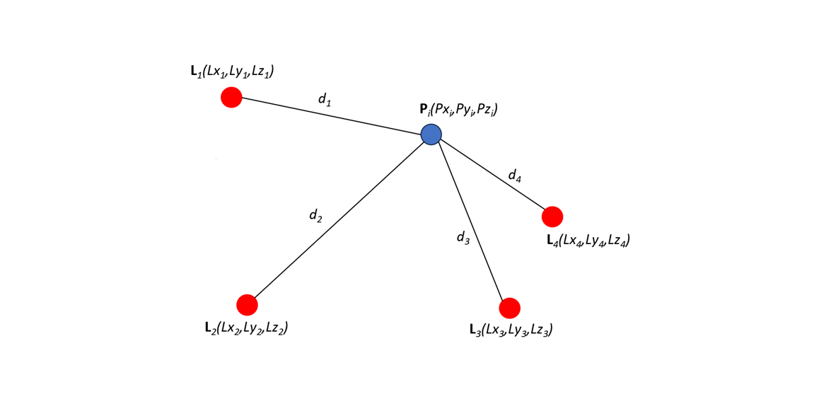
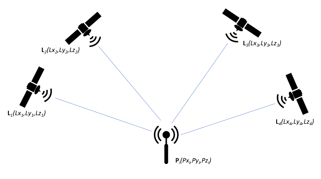
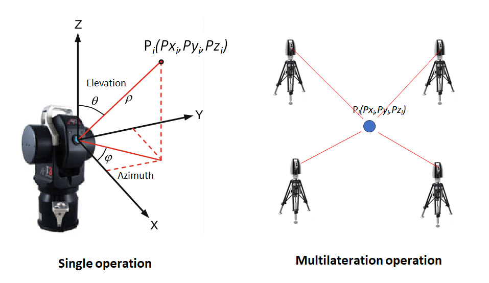
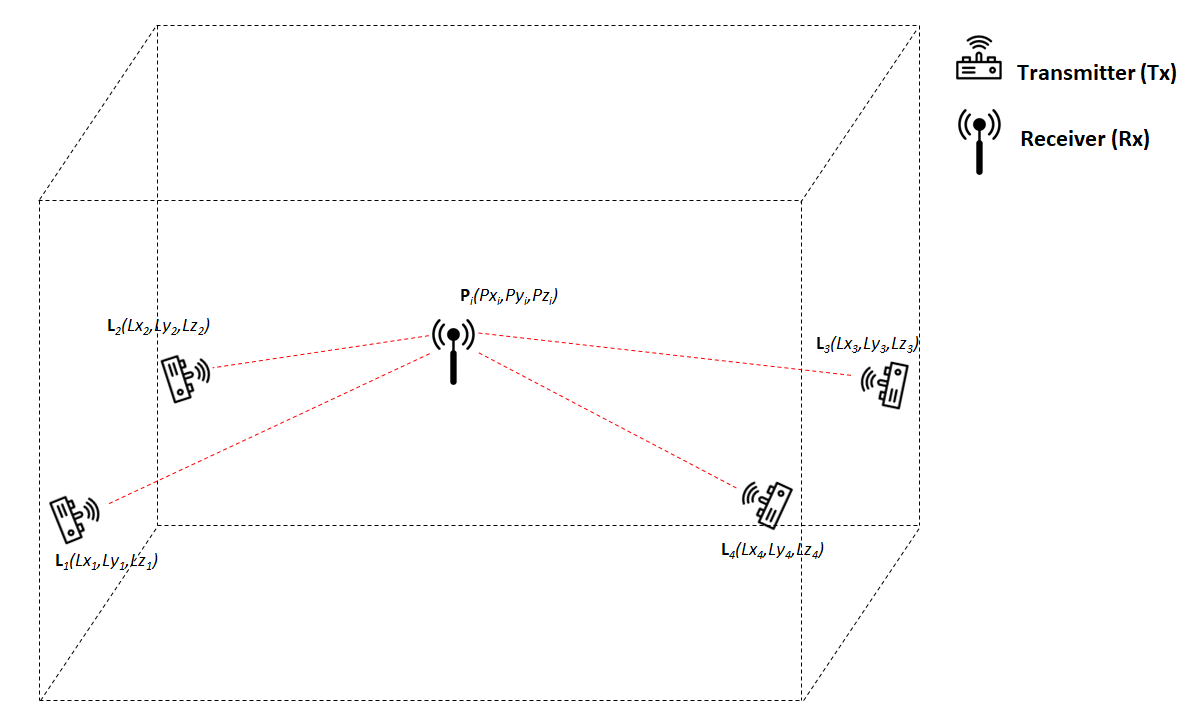
Figure 1 below shows general multilateration method. In this figure, the position of a subject P in $x,y,z$ coordinate system will be determined from the distance between P and other four transmitters or beacons with known positions.
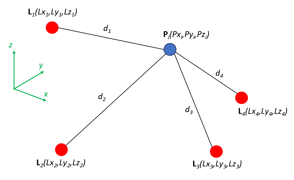
The general equation of multilateration system is as follows:
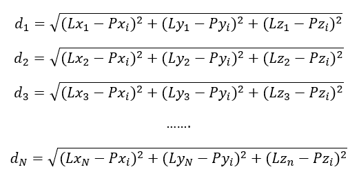
The equation above is non-linear. There are several methods to solve this non-linear equation to find the location of P. One of the common methods is by using linearisation with Taylor expansion method as for the case of GNSS positioning.
General position determinations by using multilateration method have these characteristics [1]:
- Consist of N numbers of transmitter or beacon or signal source (with known positions) and a subject whose position to be determined.
- The M number of transmitter or beacon simultaneously transmit a signal or lights from which the distance between the subject and the transmitters or beacons will be calculated.
- The position of the subject is then determined by means of least-square principal method.
In case of GNSS, the equation eq. 1 above becomes:
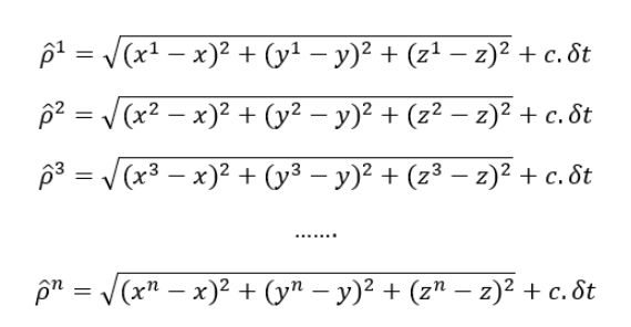
Where $d$ is replaced by $\rho$ that is called pseudorange because there is a clock offset on the receiver side.
Figure 2 below shows the GNSS-based position determination by incorporating multilateration system. In this figure, from the nature, the transmitters or beacons always comes from above a GNSS receiver.
To solve the multilateration equation as presented in eq.2, linearisation by using Taylor expansion method is used. After the linearisation procedure, eq. 2 can be re-written as follows:
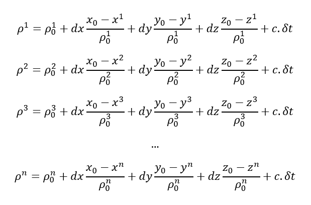
In Matrix form, eq. 3 above can be written as:
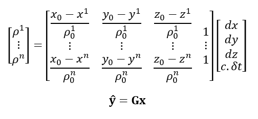
Where G is the design or geometry matrix of navigation equations.
The equation above should be overdetermined (involving >4 transmitter or beacon or satellites) to leverage the error averaging effect (least-squared method).
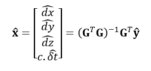
The solution of x can be calculated as:
The error of the least-square fitting to solve the above equation eq. 5 is:
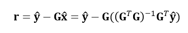
The variance-covariance matrix P of r is calculated as:
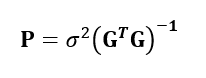
Where $\sigma$ is the error of pseudorange (the distance between the receiver and satellites) or mean-squared ranging error. In GNSS, since the speed of the signal is constant, the error mainly comes from the error in estimating the travel time of the signal from the satellites to the receiver.
Hence, $\sigma$ can be written as:
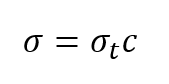
Where $c$ is the speed of the GNSS ranging signal and $\sigma _{t}$ is the error in determining the signal travel time from a GNSS satellite to a GNSS receiver.
The variance-covariance matrix P can be described in high-level as:
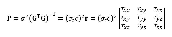
The matrix r is called the matrix of error amplification or in GNSS term it is called DOP (dilution of precision). This matrix amplifies the pseudorange error (pseudorange is the distance error between the satellite and receiver before correcting the receiver clock-offset).
From matrix r, the dilution of precision of positons in various directions can be determined. This matrix relates the geometrical relations between a subject and its beacons (a GNSS receiver and satellites) in term of final positon error behaviour.
For example, the horisontal dilution of precision in x-direction is $r_{xx}$. As such, the mean-squared error in x-direction is $\sigma _{t}c \times r_{xx}$.
In summary, the accuracy of GNSS positioning is fundamentally depends on two aspects:
- The error of determining pseudorange (ranges) between a receiver and satellites due to the error in timing determination of signal travelling.
- The geometrical configuration of the satellites known as dilution of precision (DOP). DOP acts like an error amplification of the pseudorange error.
Surprisingly, the invers of matrix r is equal to moments and products of inertia of the centre of mass of a mechanical part L [1,2] and can be formulated as:
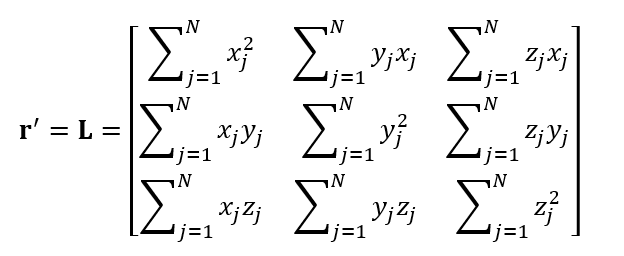
Where $N$ is the number of beacons or transmitter or signal sources with known positions.
This equation is very familiar in the field of mechanics and is essential in understanding factors affecting the error of positions obtained from multilateration method.
That is, it is interesting that we can relate the multilateration calculation in GNSS filed to the mass moment of inertia calculation in the field of mechanics.
From L matrix in (eq10), DOP error has several properties that are [1,2]:
- Dependency on the number of the transmitter (satellite).
- Dependency on the configuration of the subject-beacons (receiver-satellites).
- Difference between horizontal (planar) and vertical error.
- Affected by the dropping out of a beacon (satellite) from the beacon (satellite) configuration.
Uncertainty of DOP in multilateration method
From the analysis of the matrix L = r’, the DOP uncertainty characteristics are as follows [1,2]:
- Increasing cone angles will significantly reduce the DOP and hence the root-mean square error of calculated positions. That is, the more spread the beacon (satellite), the smaller the DOP error.
- Increasing the number of beacons (transmitters or signal sources) will reduce the DOP but not as significant as increasing the cone angle. The DOP error is proportional to $1/\sqrt{N}$ where N is the number of beacons. But, there is a limit on how many beacons are available that can reduce the DOP error.
- The smallest DOP is obtained when the beacon is symmetrically spread around a unit circle distance with respect to a subject in the same plane.
- When most beacons are above (or below) the subject whose position to be determined, the vertical DOP dominates and is larger than horizontal DOP.
- The drop out of beacons that is the most spread in the subject-beacons configuration will have a significant effect on DOP error increase. That is, from mechanics point of view, the beacon that greatly affect the change of centre of mass moment of inertia.
Multilateration by using a laser tracker system for large scale dimensional metrology
Laser tracker has been known for large-scale dimensional measurement in large manufacturing and assembly processes [3]. Laser tracker has a large similarity with a theodolite system.
Laser tracker is a portable coordinate measuring system that measures the $x,y,z$ position of a cooperative target, commonly in a form of spherically mounted retroreflector (SMR) or cat’s eye reflector [3].
The laser tracker measure both the distance to the cooperative target and also two angles in spherical coordinate system.
The main laser tracker components are a ranging unit based on laser interferometry system (commonly use a He-Ne laser source), two-axis steering mechanism to measure the azimuth and elevation angle of a target, a cooperative target and environmental sensors, such as pressure, temperature and humidity sensors.
The main advantages of laser tracker system are high accuracy and short metrological traceability chain [3].
Regarding accuracy, since a laser tracker uses a laser interferometry system, the accuracy of a laser tracker significantly depends on how accurate we can determine the wavelength of the laser used on the tracker in measurement environment.
The wavelength of light in a measuring environment directly depends on the refractive index of the environment. This refractive index largely depends on the temperature, pressure, relative humidity and the air composition of the measuring environments.
The are two possible operation modes of laser tracker. Figure 3 below shows the possible operation modes for laser tracker system. In this figure, we can use laser tracker in either single operation mode or multilateration mode.
Laser tracker in single operation mode
Principally, we can measure a target position with a single laser tracker (since it also measures two angles, azimuth and elevation angles, in spherical coordinates).
However, in single operation mode, the position error is large due to opto-mechanical error of the construction of a laser tracker [3,6].
The geometrical misalignment of opto-mechanical components of laser tracker contribute significantly to the total position error of a measured target.
Common lists of geometrical error of laser tracker are wavelength error (range offset), axis non-orthogonality and offset error, azimuth and elevation angle scale error and beam angle and axis offset error and others [6].
In addition to the geometrical misalignment, distance measurement due to wavelength determination errors also contribute to the total position error measurement. This wavelength error is caused by variation on the condition of measuring environment such as pressure, temperature and relative humidity variations [4,5].
To reduce this position error in single operation mode, an error mapping that quantifies the error of the opto-mechanical system is applied. From this error mapping, software corrections are applied to the measured position of a cooperative object.
This error mapping requires a significant modelling and calibration effort.
In addition, all environment variations should be measured so that the wavelength of the laser can be compensated.
Laser tracker in multilateration operation mode
Another operation mode of laser tracker is by using multilateration method. In this mode, we only use ranging (distance) measurement capability of a laser tracker.
Figure 3 above shows the illustration of a multilateration measurement with four laser trackers.
In laser tracker multilateration, laser tracker is as the beacon and the cooperative target is as the subject.
With multilateration method, many geometrical errors of a laser tracker can be minimised and hence reduce position measurement errors. Very often, most of laser tracker positioning errors comes from rotational axis related errors contributions [3]. However, we need multiple laser tracker to infer the position of a cooperative object.
The unique aspect of multilateration used in a four-laser tracker configuration is that the first laser tracker is used as the centre of the coordinate frame (0,0,0) and the other three laser trackers positions are determined simultaneously when the position of the target is calculated.
This step is often called as self-calibration where unknown parameters of measuring instruments are determined by using overdetermined measurements, such as performing measurements at different positions and targets.
The mathematical model of multilateration by using four laser trackers are as follows:
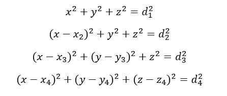
Where $x,y,z$ are the coordinates of a cooperative object whose position to be determined, $d_{i}$ is the distance between the object and the $i-th$ laser tracker and $x_{i}, y_{i}, z_{i}$ are the coordinates of the $i-th$ laser tracker with respect to the 1st tracker position as the reference.
Note that, form eq.11, three laser trackers are at the same height (the same $x-y$ plane) and the 4th laser tracker is at different height with respect to the other three laser trackers.
In matrix system representation of the above eq. 11 is as follows:
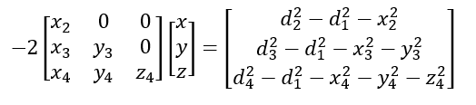
From eq. 12 above, we can observe that the 4th laser tracker should have different height with the other laser trackers in order to avoid matrix singularity in the left-hand side of eq.12.
From eq. 12, the solution of the matrix equations will both solve the object positions as well as the other three laser trackers position with respect to the 1st laser tracker as the reference.
Uncertainty sources
Similar to multilateration in GNSS position measurements, although the uncertainty of range measurement with laser tracker will be small (since the range measurement is based on laser interferometer), the uncertainty will be amplified due to the laser tracker configurations.
That is, the dilution of precision due to the configurations amplifies the range error.
Since the range (linear distance) measurements of laser tracker use laser interferometer system, environmental conditions affecting the laser wavelength are also the main uncertainty contributions for laser tracer measurement.
That is, the variation of pressure, temperature, relative humidity and air compositions in measurement environment are relevant uncertainty contributors for laser tracker measurements.
READ MORE: Uncertainty estimation of laser interferometry measurements
Potential multilateration by using a ranging-signal system for large scale dimensional metrology
We have discussed multilateration measurements in GNSS-based and laser tracker-based position determination of an object.
Also, we have seen that there is a close relation between multilateration measurement with knowledge in the field of mechanics. This fact shows that science is related and applicable in different applications.
With respect to large-scale dimensional measurement application in manufacturing, multilateration implementation in GNSS and current laser tracker system have some disadvantages.
The disadvantages of GNSS systems for large-scale dimensional measurement are as follows:
- GNSS signal is very weak indoors so that signal accuracy will be significantly degrade for indoor application. Recently, a low-earth orbit (LEO) GNSS system is being investigated for indoor positioning applications. However, in manufacturing, large-scale dimensional measurement requires millimetre to micrometre accuracy. This level of accuracy is difficult to achieve with GNSS indoor measurement.
- GNSS signal processing is complex, requiring GNSS signal acquisition, tracking and demodulation to calculate positions.
- GNSS system requires a large and complex infrastructures and involve inter-governmental cooperation for the GNSS system operations and maintenances.
Meanwhile, the disadvantages of laser tracker systems for large-scale dimensional measurement are as follows:
- Laser tracker is very expensive for a single unit. In multilateration, we need at least four laser tracker that will quadruple the total cost.
- Since the range measurement is based on laser interferometer, the sensitivity to environmental disturbances is very high.
- Requires a special cooperative target to return the laser back to the laser tracker to calculate the distance to an object.
- Laser tracker required a line-of-sight to a cooperative target. A barrier between a laser tracker and an object to track will fail the distance measurement by the laser tracker.
Proposed multilateration method for in-door large-scale dimensional measurement
A potential solution to implement multilateration position measurement at low cost and high accuracy for large-scale dimensional measurement in large scale manufacturing and assembly applications are by combining the advantages of ranging signal system in GNSS and multilateration model in laser tracking systems.
Figure 4 below shows the concept of the proposed low cost and high accuracy multilateration 3D position measurement for large-scale dimensional measurements.
In figure 4, the beacons, instead of using laser trackers, we use an RF transmitter. This RF transmitter can be in the form of of-the-self software defined radio (SDR) that can be obtained at low-cost, for example RTL-SDR and HACK-RF.
The object can be of-the-self receiver that can be the same form of the beacon, that is a low-cost and affordable SDR devices.
The transmission-receiver system can use low RF signal. Because this low RF signal will have high capability in penetrating obstacles that are common in indoor settings [7].
The RF transmitter will transmit a type of ranging signal where from this signal, the receiver can receive the signal and a computer can process the signal to calculate the range between the transmitter and receiver.
We can set the first transmitter as the reference (as in the laser tracker multilateration measurement model) and infer the position of the other three transmitter at the same time when we calculate the receiver (subject) position.
Of course, we may need >4 RF transmitters since we will have more unknows that is the clock bias of the receiver. However, the transmitter is affordable and should be not a problem.
The advantages of this potential multilateration system with a dedicated and low-cost ranging signal system are:
- The system can be realised at low cost. Both transmitters and receivers can use affordable SDR devices.
- High accuracy position measurement of a subject (the location of a receiver) can be obtained. We can design a ranging signal with high frequency baseband to increase the resolution of the ranging calculations.
- There will be no line-of-sight requirements between a transmitter and receiver unlike the case of laser trackers and a cooperative target system. This capability increases the flexibility of the measurement system as, for indoor settings, obstacles are very common.
- The system is highly portable and easy to setup.
- At low frequency RF, in MHz, the signal will have a high capability in penetrating obstacles [7].
- The system is robust to the variation in a measuring environment, such as ambient temperature, pressure and relative humidity as well as air compositions variations.
Possible uncertainty sources
The main uncertainty sources will be the same as inherently found in a multilateration system. However, this system will be less affected by measurement environment conditions.
Potential uncertainty sources are:
- The error in ranging measurements as well as the geometry of transmitter-receiver (dilution of precision).
- The electronic noise of the receiver and transmitter that contribute to the signal noise and calculation of the range.
- Signal quality degradation effect when a very thick and solid obstacle exists between a receiver and transmitter. In addition, electronics noise can also distort the generated and transmitter ranging signal form the transmitter and hence affected the ranging accuracy.
- The bandwidth of the ranging signal. The higher the bandwidth, the higher the ranging accuracy can be obtained and otherwise.
Finally, Applications: robot metrology, aerospace assembly, large scale CMM calibration and many others.
READ MORE: Measurement uncertainty estimations: GUM method
Conclusion
In this post, we have briefly discussed the concept of multilateration method to determining the position of a subject from four or more beacons with known positions and known distance to the subject.
It is interesting to show that multilateration model, commonly used in GNSS positioning, is closely related to the model of mass of moment of inertia from the field of mechanics. This fact shows that science and engineering methods are related to each other and is applicable to different fields.
We first discuss the multilateration method implemented in GNSS positioning and then discuss the multilateration method implemented in large-scale manufacturing with laser trackers.
Finally, an idea of combining the advantages of multilateration implemented for GNSS positioning and the advantages of multilateration modelling implemented for laser tracker has been presented. The idea is to implement a multilateration method for accurate large-scale dimensional measurement at low cost and with robustness to environmental disturbances.
References
[1] Lee, H.B., 1975. Accuracy limitations of hyperbolic multilateration systems. IEEE Transactions on Aerospace and Electronic Systems, (1), pp.16-29.
[2] Lee, H.B., 1975. A novel procedure for assessing the accuracy of hyperbolic multilateration systems. IEEE Transactions on Aerospace and Electronic Systems, (1), pp.2-15.
[3] Muralikrishnan, B., Phillips, S. and Sawyer, D., 2016. Laser trackers for large-scale dimensional metrology: A review. Precision Engineering, 44, pp.13-28.
[4] Muralikrishnan, B., Czapla, B., Lee, V., Shakarji, C., Sawyer, D. and Saure, M., 2024. Laser Tracker and Terrestrial Laser Scanner Range Error Evaluation by Stitching. Sensors, 24(10), p.2960.
[5] de Souza, M.M., Muralikrishnan, B., Lee, V. and Sawyer, D., 2023. Laser tracker relative range error evaluation by the back-to-back, common path single pass, and common path double pass methods. National Institute of Standards and Technology.
[6] Hughes, B., Forbes, A., Lewis, A., Sun, W., Veal, D. and Nasr, K., 2011. Laser tracker error determination using a network measurement. Measurement science and Technology, 22(4), p.045103.
[7] Syam, W.P., Scott, D., Conesa, A.P., Rodriguez, I., López, M., Juan, E. and Ioannidis, R.T., 2022, September. Low rf-based navigation for emergencies in difficult environments. In Proceedings of the 35th International Technical Meeting of the Satellite Division of The Institute of Navigation (ION GNSS+ 2022) (pp. 1729-1745).
You may find some interesting items by shopping here.