Correlator outputs for clean and spoofed GPS L1 C/A signals
The pseudorange and navigation data determination from global navigation satellite system (GNSS) signals are calculated from the correlator outputs at the tracking stage of the GNSS signal processing.
The pseudorange and navigation data determination from global navigation satellite system (GNSS) signals are calculated from the correlator outputs at the tracking stage of the GNSS signal processing.
Any spoofing attacks that try to overlap the correlator output of an authentic signal at the tracking stage (we called it as over-lapping spoofing attack) will disrupt or degrade the pseudorange estimation and/or navigation data contained in a GNSS signal and hence reduce the accuracy of position solutions or, the worst, produce false position solutions.
This over-lapping spoofing attack typically has a code delay within $\pm 1$ chip of a pseudo-random number (PRN) code of an authentic signal.
In this post, we will visualise the shape of correlator outputs for GPS L1 C/A signals at different events, which are:
- When only clean signal presents
- When a spoofer presents with code delay $\pm 1$ chip of its authentic counterpart signal
- When a spoofer presents with code delay $o$ chip of its authentic counterpart signal (matching the authentic signal code delay)
By the end of this post, we will understand the effect of over-lapping spoofing on the correlator outputs of GPS L1 signals and will have an idea on how to detect this spoofing event.
In addition, we will see that it is very difficult for a spoofer to exactly match the Doppler of an authentic signals [1].
Hence, even if a spoofer can match the code delay of an authentic signal, there will be a slight mismatch with the Doppler of the authentic signal and hence there will be a distortion on the correlator outputs on the Q channel of GPS L1 signal [1]. This distortion on Q channel can be exploited to detect spoofing.
Let us go into the discussion!
READ MORE: Public datasets for spoofing and evil waveform (EWF) signals
Tracking stage of GPS L1 C/A signal
In this post, we will use a signal from TEXBAT ds3.bin dataset [2]. This ds3.bin dataset is am approximately 10-minute period of GPS L1 C/A signal.
In this signal, a spoofer is injected into this clean signal at 100s and the spoofer starts to overlapped with the correlator output of the authentic signal at 118s. At 120s, the spoofer’s code delay matches the authentic signal’s code delay. Finally, the spoofer captures the correlator output of the authentic signa at approximately 169s.
The correlators of the tracking of this signal are calculated at different 11 delay taps: five early and five late delay taps equally spaced for 0.2 chip each and one at prompt (zero) delay tap.
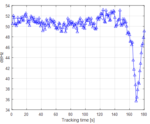
Figure 1 below shows the tracking results of the signal for 180s. in Figure 1, both the prompt (zero delay tap) correlator outputs on the $I$ channel and the square-root of the prompt, early and late code delay of the $I/Q$ channel are presented.
As can be seen in figure 1, starting at 188s, the energy of the correlator output starts to increase due to the energy contribution from the spoofer signal.
The maximum energy is start at 120s until 140s where the spoofer matched the code delay of the authentic signal (hence the total energy of the correlator output is due to the contribution of both the spoofer and authentic signal).
Finally, the spoofer captures the correlator output at around 169s as can be observed the energy of the correlator output is at minimum.
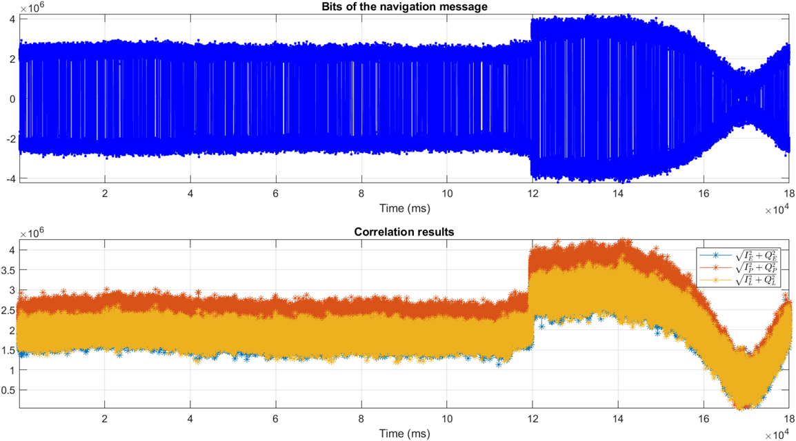
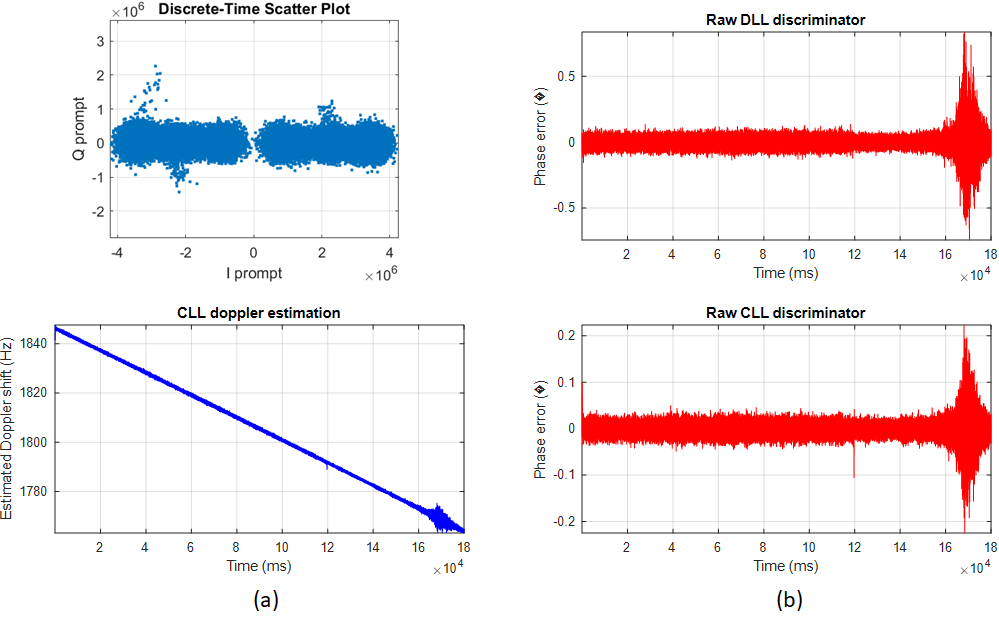
Figure 2 below shows other indicators of when the peak event of the spoofer successfully captures the authentic signal’s correlators.
From figure 2a, the tracked $I/Q$ constellation shows an elongated shape due to the contribution of the spoofer signal and the estimated Doppler starts to jump at around 169s. In addition, figure 2b shows a jump on both the code delay and carrier phase error discriminator at around 169s where the spoofer captures the authentic signal’s correlator.
Similar behaviour of the C/N0 calculated from the tracking process. The C/N0 when the authentic signal has been captured by the spoofer is at minimum (significantly dropped) compared to the C/N0 where the spoofer is not presents or where the spoofer does not start to capture the authentic signal’s correlator.
Hence, C/N0 is also a good representation of the existence of a spoofer in GNSS signals.
The correlator output of un-spoofed signals
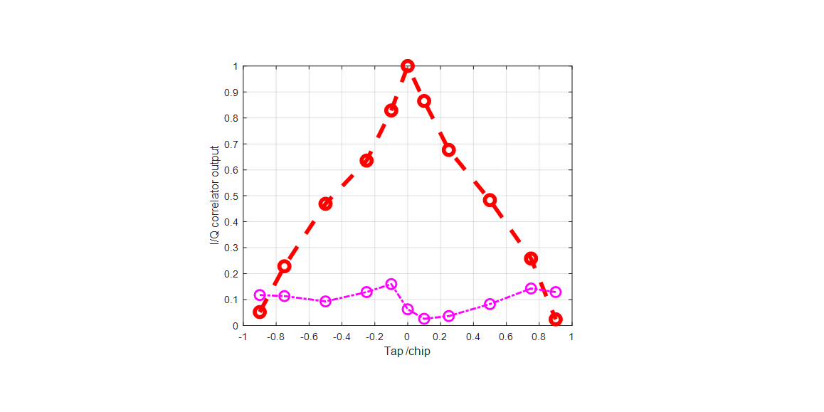
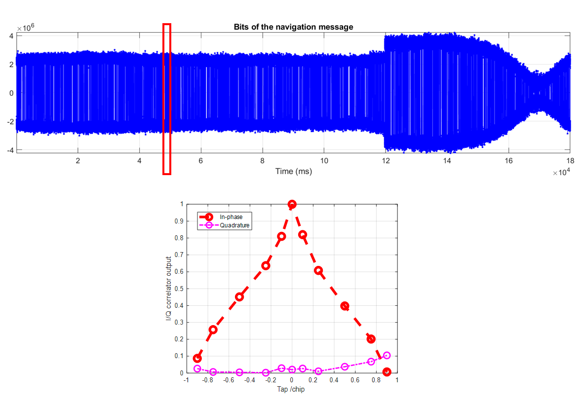
Theoretically, a clean signal (where a spoofer is not present) will have a perfect triangle shape. Note that the shape of this correlator output is normalised with respect to the output of the prompt correlator (where the delay between the signal and local replica is zero).
Figure 4 below shows the shape of the correlator output. We can observe that since there is no spoofer presents, the shape of the correlator is close to a perfect triangle.
There is a slight distortion on the correlator shape due to environmental disturbance on the signal, such as atmospheric effects and noises from the environment and hardware receiver.
READ MORE: GNSS spoofing: a fatal attack on GNSS system that is difficult to detect
The correlator output of spoofed signals
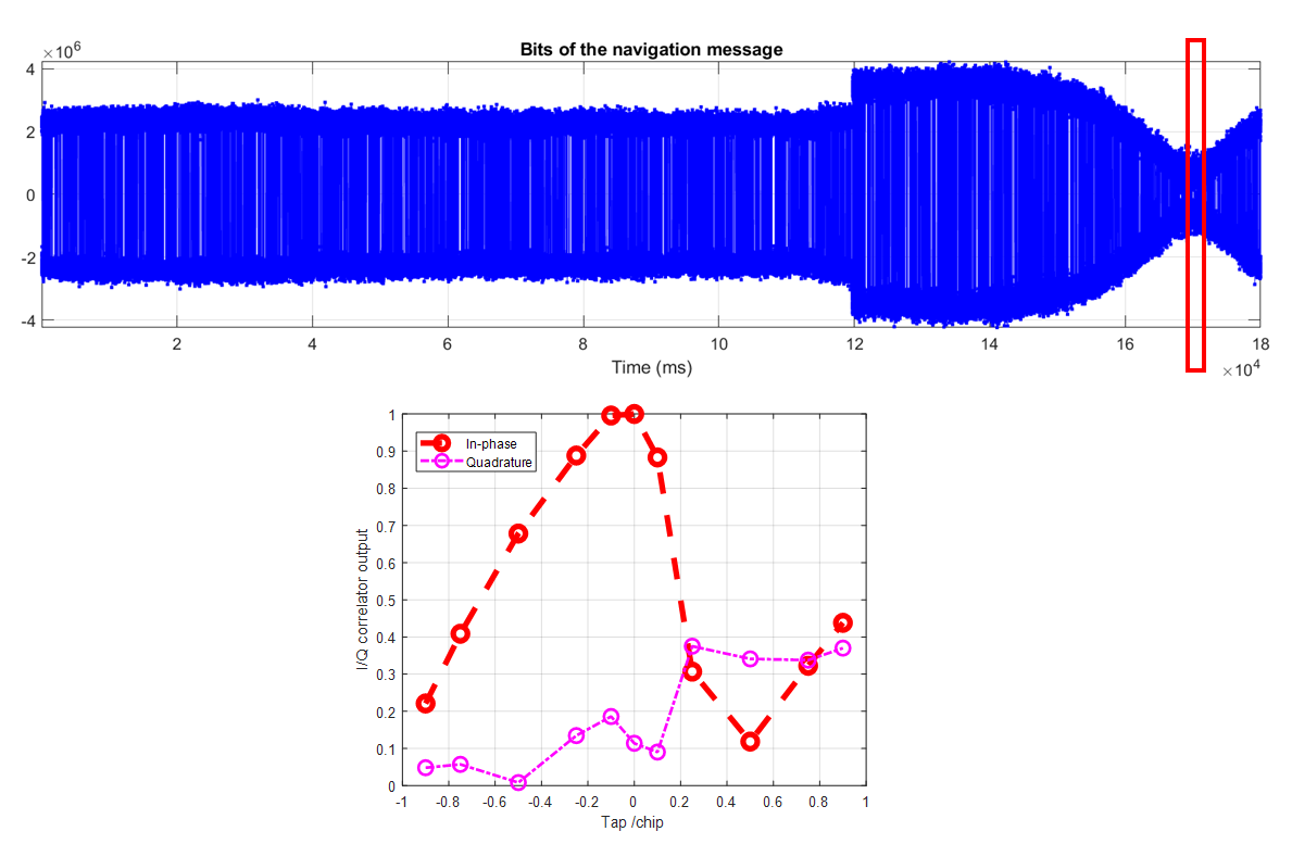
The significant distortion of correlator outputs of a spoofed GPS L1 signal will be presents, especially when the spoofer starts to capture the correlator outputs of the authentic signal.
Figure 5 below shows the significantly distorted correlator output at 169s where the spoofer successfully captures the authentic signal’s correlator outputs. From figure 5, the distortion is significant both on the $I$ and $Q$ channels.
After only few second of this event, the software receiver tracks the spoofer signal instead of the authentic signal. Hence, the calculated pseudorange and position, time and velocity (PNT) deviates from expected.
These false solutions are the real danger of spoofing attack.
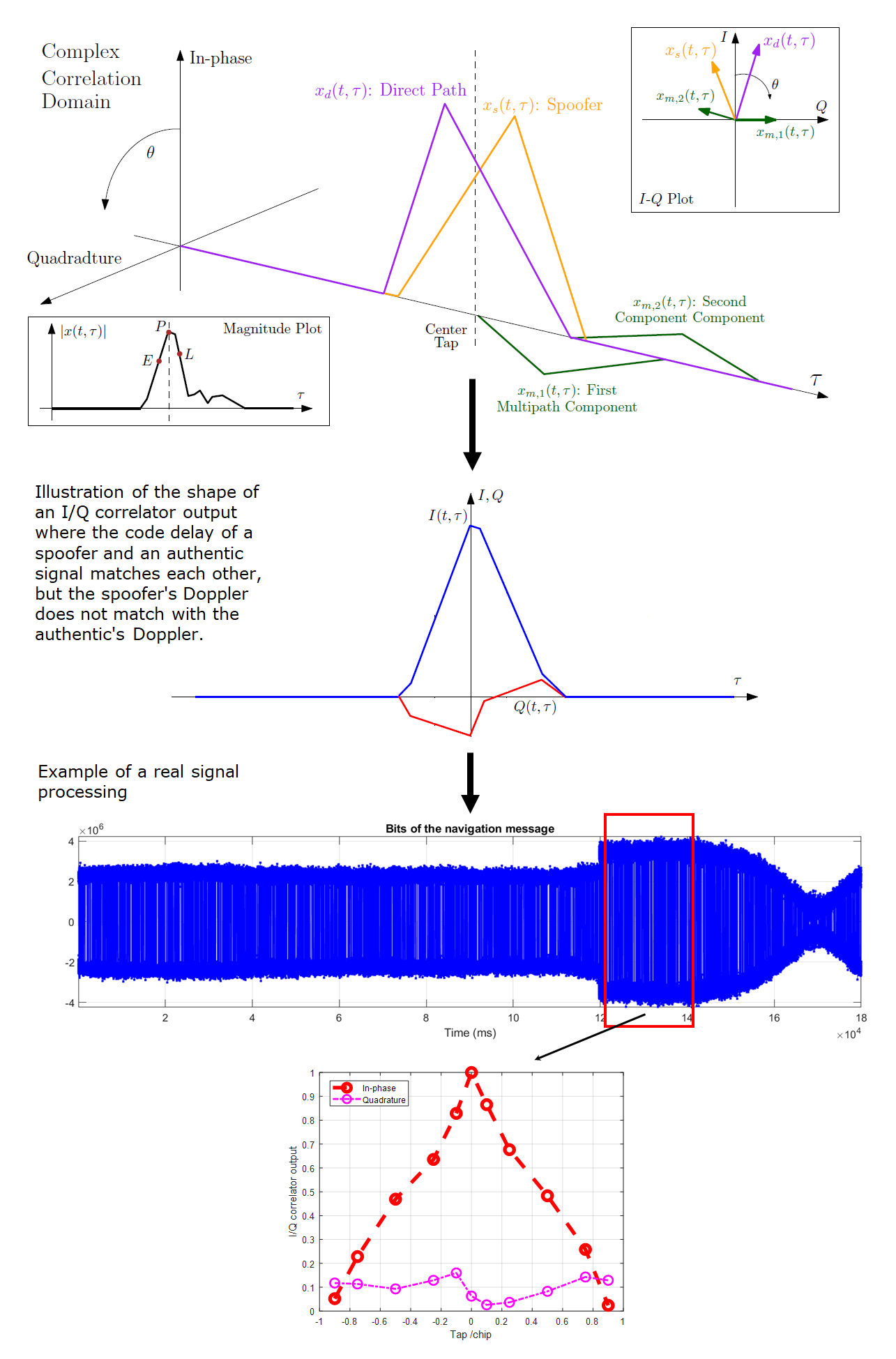
The third condition of an over-lapping spoofing event is shown in figure 6 below. In figure 6, the illustration of the difficulty of a spoofer to exactly match the Doppler of an authentic signal is presented (figure 6 top) [1].
As stated in [1], it is very difficult for a spoofer signal to exactly match the Doppler of an authentic signal. Since the Doppler between the spoofer and authentic signal is not exactly match, there is a leak of signal energy to the $Q$ channel (figure 6 middle).
The effect of this situation (match code delay, but slightly unmatched Doppler) on the correlator outputs is that the correlator outputs on the $I$ channel are close to a triangle shape, but the correlator outputs on the $Q$ channel is distorted from a perfect straight line (ideally, the Q channel should be zero after perfectly being tracked).
Hence, any parameters that can capture the distortion of the correlation peak are potential to be used for over-lapping spoofing detection.
READ MORE: Evil waveform (EWF) in global navigation satellite system (GNSS) signal
Conclusion
In this post, the shape of correlator outputs of a spoofed GPS L1 C/A signal has been presented and discusses. We can see that for over-lapping spoofing attack, the shape of the correlator outputs will be significantly affected.
The correlator output shapes of a clean signal, over-lapping spoofed signal at zero delay and over-lapping spoofed signal at $\pm 1$ chip delay will significantly differ among each other.
Finally, any parameters that can capture this correlator output distortion can be potentially used for over-lapping spoofing detection.
References
[1] Wesson, K.D., Shepard, D.P., Bhatti, J.A. and Humphreys, T.E., 2011, September. An evaluation of the vestigial signal defense for civil GPS anti-spoofing. In Proceedings of the 24th International Technical Meeting of the Satellite Division of the institute of navigation (ION GNSS 2011) (pp. 2646-2656).
[2] Humphreys, T.E., Bhatti, J.A., Shepard, D. and Wesson, K., 2012. The Texas spoofing test battery: Toward a standard for evaluating GPS signal authentication techniques. In Radionavigation Laboratory Conference Proceedings.
You may find some interesting items by shopping here.