Real-time decoding of NAV messages of Septentrio receiver in C programming language
Septentrio receiver is one of the most used global navigation satellite systems (GNSS) receivers, including u-blox and Novatel GNSS receivers.
Septentrio receiver is one of the most used global navigation satellite systems (GNSS) receivers, including u-blox and Novatel GNSS receivers.
This GNSS receiver, including other receivers from different manufacturers, are mainly used to give position, navigation and timing (PNT) solutions calculated from ranging signals of various GNSS satellite constellations, such as GPS, GALILEO, GLONASS, BEIDOU, QZSS and other constellations, including satellite-based augmentation (SBAS) constellation, such as EGNOS (EU and UK), WAAS (in US) and other SBAS system.
However, if we want to create an integrated GNSS user product and application that really want to seamlessly integrate Septentrio receiver solutions into the product and application, we need to be able to directly receive and extract navigation messages from the Septentrio receiver.
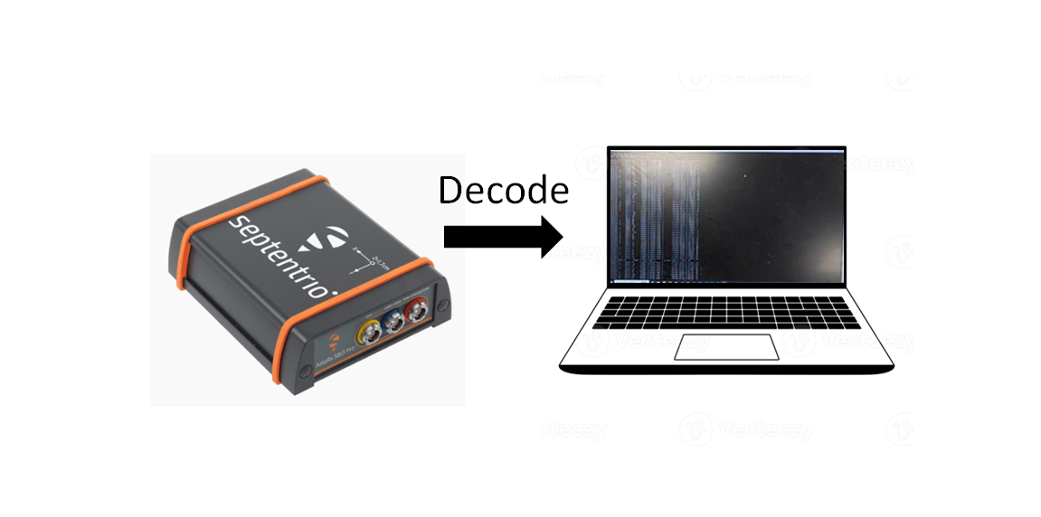
In this post, we will present and show how to receive and extract (decode) navigation messages from a Septentrio receiver in Real-time.
We focus on the first 8 bytes that are found in every Septentrio navigation message block.
The real-time navigation messages receiving and decoding from the receiver is implemented in C programming language providing COM port programming.
COM port is a type of serial communications. Other example of serial communication is USB port.
In addition, the settings on the Septentrio receiver and a PC to receive and decode the messages will be explained as well.
READ MORE: Reading raw binary IQ data in C/C++ with malloc() and pointer
The Septentrio receiver and the setting: baud rate and data streaming
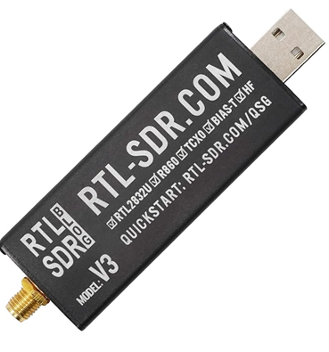
A Septentrio receiver used in this post is the one that is already in the form of a rugged case as shown in figure 1. In figure 1, the Septentrio has three COM ports and one USB port.
The USB port should be connected to a laptop to power the Septentrio as well as to connect to the Septentrio software. Hence, only COM1 we can use in this case as COM2 and COM3 have been used for USB serial connection.
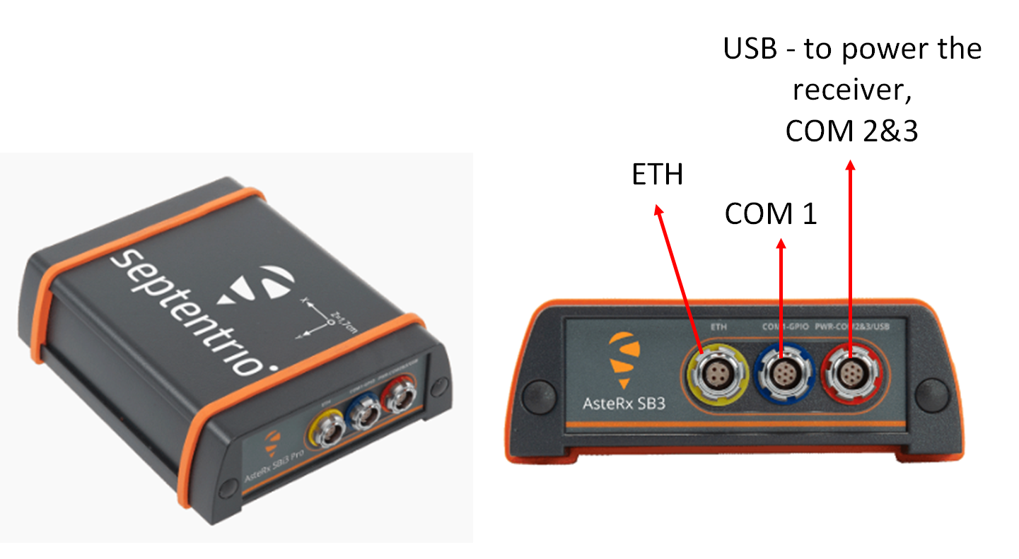
Note that there are other types of Septentrio receivers that are only in the form of a module board. For this type, we may have to use or make an adapter for their COM port.
Data streaming setting
Before going to COM port communication, firstly, we need to set the Septentrio receiver to stream navigation messages (in Septentrio proprietary format called “SBF”) to one of its COM ports.
In this case, we can set the receiver to stream navigation messages to COM1 port.
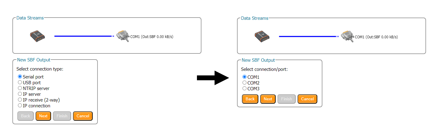
Figure 2 and figure 3 below show the steps on how to stream navigation messages (the SBF message) to serial ports of the Septentrio receiver.
To set the Septentrio streaming SBF messages, as shown figure 2, from the Septentrio software interface, we need to go to “NMEA/SBF out” and create “New SBF stream”.
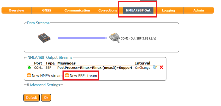
After we select the “New SBF stream”, we can select the type of ports. In this case we select “serial port” and then, select the “COM1” as shown in figure 3.
COM port settings
The first thing to do in COM port programming is to adjust the baud rate between devices that will communicate each other. This baud rate determines how fast a communication channel can transfer bits (data).
For example, a 9600 baud rate means that the serial port can transfer up to 9600 bits per second.
The higher the baud rate, the faster the data transfer will be. However, at the same time, the reliability of the data transfer will reduce.
The baud rate between the devices that will communicate via the COM port should be the same.
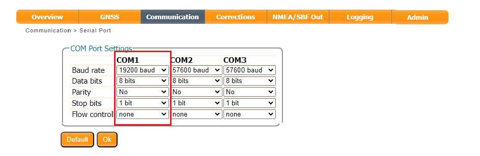
Figure 4 shows the settings of the baud rate for the COM port of the Septentrion GNSS receiver. In figure 4, the option to configure the baud rate is in “Communication” section in the Septentrio receiver software.
It is important to note that the determination of the optimal baud rate needs to consider aspects that are:
- The reliability of the communication channel. The less reliable means that the probability of error bits to be received will be high, and otherwise.
- The prevention of buffer underflow. This situation happens when a sender device (in this case the Septentrio in use) send data at a speed that is lower than the processing speed of a receiver device (in this case a laptop). This is called data starving.
- The prevention of buffer overflow. Opposite to the underflow condition, overflow happens when the sender device send/transmit data at a speed that is higher than the processing speed of a receiver device (in this case the laptop). This situation will cause data will be held in the COM port buffer of the receiver device and, at some point, will exceed the buffer capacity.
Based on the above three factors, to determine the optimal baud rate settings, trial and error methods has been used.
From the trial-and-error test, a baud rate of 19200 bits per second is selected that can provide a robust serial communication between the Septentrio receiver and the laptop and at the same time avoiding underflow and overflow in the serial port buffer at the laptop.
READ MORE: TUTORIAL: MATLAB software inter-connection and cooperation with PYTHON software using pyenv()
Setting the PC COM port baud rate
At the laptop (the one which receive the data from the Septentrio receiver), the same baud rate on the COM port should be set identical to the one set at the Septentrio.
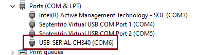
To set the baud rate of the COM port at the laptop, we can go to “device manager” and double click the COM port that is used for the communication.
Figure 5 shows the COM port selection (in this case COM6, but the COM number may be different for different laptops) to set the baud rate of the COM port.
Note that from figure 5, there are two virtual USB COM Ports. These two virtual ports are for the USB connection between the laptop and Septentrio.
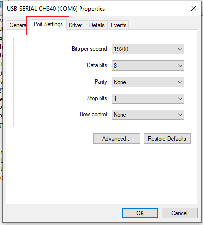
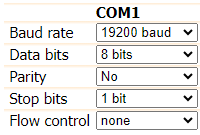
And, Figure 6 shows the window to set the baud rate of the COM port in the laptop. Note that other properties that are data bits, parity, stop bits and flow control should be the same to the Septentrio COM port settings.
READ MORE: Correlator outputs for clean and spoofed GPS L1 C/A signals
COM port communication in C
In this section, the method to connect to the COM port is implemented in C language. Basically, the method used is common for all COM port programming in C language.
Here, we briefly refresh the COM port programming procedure in C and provide some code snippets.
The C library for COM port serial communication is:
#include <Windows.h>The COM port handler is created by:
HANDLE serialHandle;After the COM handler is created, we can the connect to the COM port (in this case COM6) as follows:
serialHandle = CreateFile("\\\\.\\COM6", GENERIC_READ | GENERIC_WRITE, 0, 0, OPEN_EXISTING, FILE_ATTRIBUTE_NORMAL, 0); After connecting to the COM port, we then need to set the property of the COM port to be the same as what have been set on the Septentrio’s COM port as shown in figure 7:
DCB serialParams = { 0 };
serialParams.DCBlength = sizeof(serialParams);

GetCommState(serialHandle, &serialParams);
serialParams.BaudRate = 19200;
serialParams.ByteSize = 8;
serialParams.StopBits = ONESTOPBIT;
serialParams.Parity = NOPARITY;
The above COM properties are then set into the COM port connection handler as follows:
if (!SetCommState(serialHandle, &serialParams)) {
	printf("\nCannot set the serial parameters!\n");
	CloseHandle(serialHandle);
	return;
}
Then, we need to set the timeout of how long the connection should be waiting in case there is no message. To do this, we set the timeout properties using the COMMTIMEOUTS and set these properties into the COM serial port handler as follows:
COMMTIMEOUTS timeout = { 0 };
timeout.ReadIntervalTimeout = 10;
timeout.ReadTotalTimeoutConstant = 10;
timeout.ReadTotalTimeoutMultiplier = 50;
timeout.WriteTotalTimeoutConstant = 50;
timeout.WriteTotalTimeoutMultiplier = 10;

if (!SetCommTimeouts(serialHandle, &timeout)) {
	printf("Cannot set the time outs!\n");
	CloseHandle(serialHandle);
	return;
}
The best practice in COM port communication is by implementing port listener. The port listener implementation is done by setting the COM port handler to wait until a byte or bytes are received and then read the byte/bytes from the COM port buffer to the computer (the laptop) memory to be decoded.
To implement the COM port listener, we should set the communication mask first and the set the COM port listener as follows:
Read_Status = SetCommMask(serialHandle, EV_RXCHAR);

if (Read_Status == FALSE) {
	printf("Error in Setting CommMask");
	//Close the serial port
	CloseHandle(serialHandle);

	return;
}


printf("Waiting message from Septentrio\n");

Read_Status = WaitCommEvent(serialHandle, &dwEventMask, NULL);
To check how many bytes are currently in the COM port buffer at the laptop, we can do by:
ClearCommError(serialHandle,&errors,&status);

printf("Number of bytes received: %d\n\n",status.cbInQue);
Finally, we can read the received bytes on the buffer into the computer memory one-byte at a time as follows (note that the “TempChar” is the 1-byte char data type in C/C++):
ReadFile(serialHandle, &TempChar,sizeof(TempChar), &NoBytesRead, NULL);After reading the bytes, especially the first 8 bytes, we then can decode the bytes and further process the data.
READ MORE: Beware of integer data type in computing
Decoding the Septentrio fundamental messages
After we can set and receive message bytes from the Septentrio receiver. Next, we need to decode the received messages.
Note that all the bytes use the little-endian bits arrangement.
Here, we will show and discuss the first 8-byte message from the Septentrio as these bytes are found at the beginning of all Septentrio message blocks.
Detailed message bytes for all the message blocks can be found in Septentrio SBF reference guide documents.
The first 8-bytes definitions are described in table 8. In this table, the sync bytes are the bytes that start every message block. Hence, we need to find these sync bytes to be able to find the rest of the 6-bytes and then the rest of the message bytes.
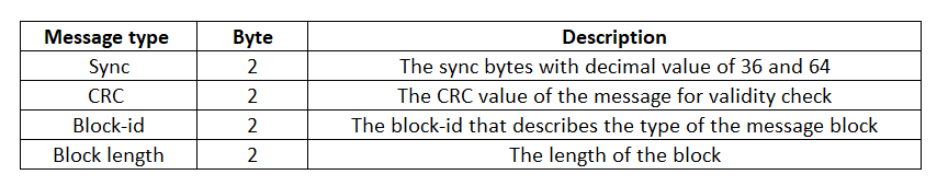
The detailed explanation of these 8 bytes are as follows:
- Sync bytes. Byte 1 and byte 2 contain the sync bytes to mark the start of every Septentrio SBF (navigation) messages. To decode this each byte, we need to convert it to a decimal value. If the two decimal values are 36 and 64 and the block length is the multiply of 4, then consider them as an SBF message block. If the block length is not a multiply of 4, then the found sync bytes are not the valid sync bytes.
- Cyclic-redundancy-check (CRC). These two bytes contain a total of 16 bits. To decode this CRC value, we need to convert the bytes into 8-bit each and then combined them into a total of 16 bit and convert again into decimal value to get the CRC value.
- Block-id. These two bytes contain the block-id (that is the block identification) and the block revision number. To decode the block-id, we need to convert the first 13 least-significant-bit (LSB) bits. That is, the 0-th bit to the 12-th bit. The rest three bits will be for the revision number.
- Block length. These two bytes contain the total block-length (in byte), from the first Sync byte to the last byte of an SBF message. Similarly to CRC, to decode the block length, we need to convert the 16-bit (combined from the two bytes data) into a decimal value to get the block length.
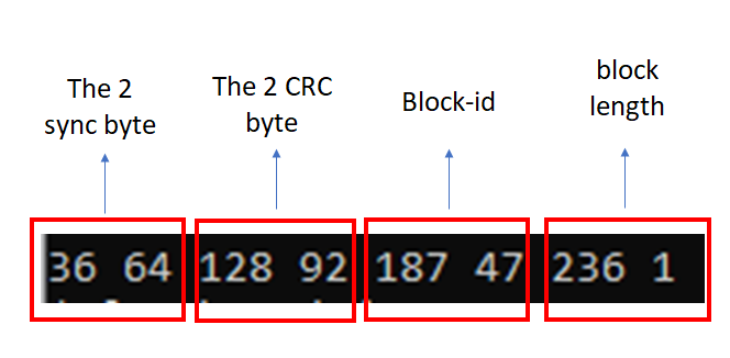
An example of the first 8-byte received from the Septentrio COM port is shown in figure 8. In this figure, all the sync, CRC, block-id and block length are shown.
As being mentioned before, decoding the sync, CRC and block-length bytes are straightforward. That is, for CRC and block-length bytes, the decoding is performed by converting each byte into 8-bits, combining each 8-bit into a total of 16-bit and then re-calculating the decimal value from the 16-bit.
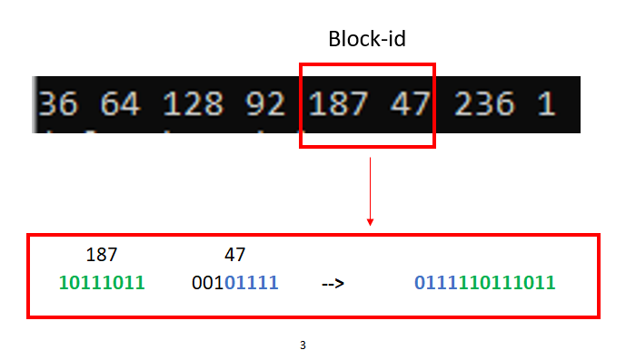
However, for the block-id, the decoding procedure is slightly different. Figure 9 shows the illustration of block-id decoding procedure.
In figure 8 and figure 9, the 2-byte (in decimal value) for the block-id is “187” and “47”.
The block length is 492, calculated from the 7th and 8th byte, value “236” and “1”. Since “492” is a multiply of 4, then the sync bytes are valid.
The block-id decoding procedure is as follows (see figure 9):
- Take the byte number 5 and 6 (from the first 8 bytes. Note that here the first byte is byte number 1). In this example, the byte number 5 and 6 are “187” and “47”.
- Convert each value from the 5th and 6th bit into two bit-groups. That are, group bit 1 for the 5th byte and group bit 2 for the 6th byte.
- Combine these two bit-groups with the arrangement as: group bit 2 + group bit 1.
- Convert the first 13 LSB bits to get the block-id.
From this example, the decoded block-id is “4027” which (from the SBF reference guide) contains all the GNSS measurements (observables) taken at the time given by the time-of-week (TOW) and week-number (WN) fields (see the SBF reference guide for details).
READ MORE: Post-correlation Carrier to Noise Density (C/N0) calculation in GNSS signal processing
Conclusion
In this post, the procedure to send in real-time NAV messages from a Septentrio GNSS receiver to a computer as well as the decoding in real time of the first 8-byte critical messages have been presented and discussed.
The main purpose is that to give the concept on how to receive navigation messages from Septentrio and decode the messages in real-time.
The benefit of knowing this method is that we can make a customised and integrated GNSS user application using one of the most used GNSS receivers for our specific needs or problem at hand.
You may find some interesting items by shopping here.