X-Ray computerised tomography (X-ray CT) for industrial part measurement: History, working principle, measurement procedure, applications and characteristics
X-Ray computerised tomography (X-ray CT) has the ability to non-destructively measure internal features of a part that is made of different materials including metals and non-metals.

X-Ray computerised tomography (X-ray CT) has the ability to non-destructively measure internal features of a part that is made of different materials including metals and non-metals.
This capability of internal feature measurements makes X-ray CTs as instrumental complementary of other coordinate measuring machines (CMMs), both contact (tactile) and non-contact (optical), for dimensional and geometrical measurements.
With X-ray CT, dimensional and geometrical as well as surface texture measurements can be performed for both external and internal features of parts. For example, the measurement of porous diameter inside an additively manufactured (AM) part or the surface texture measurement of the surface of an internal cooling channel of a turbine blade.
In this post, we will understand what X-ray CT is, why it is very important for geometrical and material quality control and what the accuracy of X-ray CT measurements are.
Let us go into this article!
READ MORE: CMM measurement uncertainty estimation: ISO 15530-3
The comparison of X-ray CT and conventional CMMs for geometrical and surface texture measurement
X-ray CT is a powerful non-destructive test (NDT) measurement tool for various types of materials, including metal, polymer and other materials [1,2].
With internal feature measurement capability, X-ray CT becomes one of the most important method for the measurement of complex AM parts, such as porosity measurements and complex internal cooling channels measurements.
Very often, AM parts have a very intricate shapes because AM process can produce virtually any parts with any types of complex geometry that cannot be made by conventional (e.g., injection moulding, turning and milling) or non-conventional processes (e.g., electrical discharge machining, laser machining and water jet machining).
In addition, X-ray CT can combine the part quality control for dimensional, geometrical and surface texture (both externally and internally) features and the material quality control of a part (for example the percentage of porosity in a solid part).
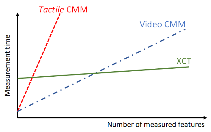
Unlike conventional CMMs, the measurement time of X-ray CT does not depend on the number of features on a part to be measured [3]. Hence, the time required to measure a part with small and large number of features will be approximately the same.
Figure 1 below shows the comparison of measurement time between an X-ray CT and other conventional CMM (both contact a non-contact). In figure 1, we can observe that the measurement time required by an X-ray CT, that is the time to scan and capture the part/object, tends to be constant irrespective of the increase of number of features to be measured.
However, X-ray CT is considered inefficient if the number of features to be measured is small (figure 1).
In general, the main capability of X-ray CT are as follows:
- The capability to measure the internal features of a part.
- The capability to perform dimensional, geometrical and surface texture measurements and material quality analysis.
- The measurement time does not depend on the number of features on a part to be measured.
READ MORE: Optical coordinate measuring machine (Optical-CMM): Two fundamental limitations

A brief history of X-ray CT for geometrical and surface texture measurement
The technology of X-ray has been around since 1895. X-ray was initially systematically studied by Wilhelm Röntgen in 1895. This X-ray becomes the basis of any X-ray CT machine and is used as an energy and radiation source in an X-ray CT system.
The main property of an X-ray CT is that its radiation ability to penetrate materials, both soft and hard materials, depends on the X-ray energy, so that the internal features of the materials can be evaluated by analysing the residual radiation, passing the materials, on a radiation detector.
Low-power X-ray CT was initially used in medicine for human tissue analysis. Now, high-power X-ray is used in an X-ray CT machine to be able to penetrate hard material, such as metal.
Until now, the main applications of X-ray CT are in medicine, material analysis, and dimensional and geometrical as well as surface texture measurements [1,2,3].
The use of X-ray CT in medicine was pioneered by Hounsfield in 1970. The use of X-ray CT for material analysis is commonly used for internal geometry analysis of materials, for examples, to analyse the degree of porosity inside the materials.
In addition, the use of X-ray for food analysis falls into this material analysis category. An example of the use of X-ray CT for food analysis is to understand the meat and bone distribution in the carcass of an animal [3].
The use of X-ray CT for dimensional and geometrical as well as surface texture measurement becomes very popular nowadays. Because, X-ray CT machines can measure internal features that are a main interest in, for example, AM processes and aerospace industries.
AM processes need to be qualified based on the level of density of the part built by these processes. Meanwhile, for aerospace, many current modern turbine blade designs have small and intricate internal cooling channels. These measurement applications drive the popularity of X-ray CT methods in manufacturing and aerospace industries.
The first dimensional and geometrical measurements by using an X-ray CT was first performed in 1991 with accuracy around $0.1mm$.
In 2005, the use of X-ray CT for these types of measurement becomes one of the main focuses after the first X-ray CT machine, dedicated for dimensional and geometrical measurement applications, was launched in a control expo in Germany [1]. This X-ray CT machine has a high-power X-ray up to 450 kV and a rotational table to automatically rotate a measured part.
READ MORE: Digital transformation of dimensional and geometrical measurements
The working principle and measurement procedure of X-ray CT
The working principle and the procedure of X-ray CT measurement are more complex than conventional CMM measurements. Besides, X-ray CT measurements require a high-performance PC to perform the calculation and reconstruction of the 3D volume model of a measured part from captured X-ray CT images.
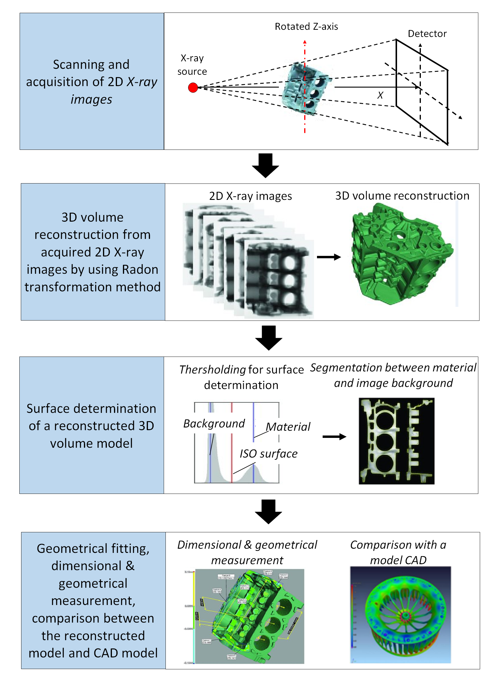
Figure 2 below shows the working principle and measurement procedures of X-ray CT machine. In figure 2, the procedure is shown from object scanning until dimensional and geometrical measurements.
The working principle
The working principle of X-ray CT is as follows. A source produces an X-ray with relatively high power to penetrate solid objects. This X-ray is radiated toward an object or part to be measured.
When the X-ray passes through the material of the object, the energy of the X-ray will reduce due to the energy absorption by the material and the energy scattering loss by the atoms of the material.
The amount of energy reduction of the X-ray depends onthe type of material, the length of the path that the X-ray travels inside the material, the density of the material and the initial energy of the X-ray (figure 3).
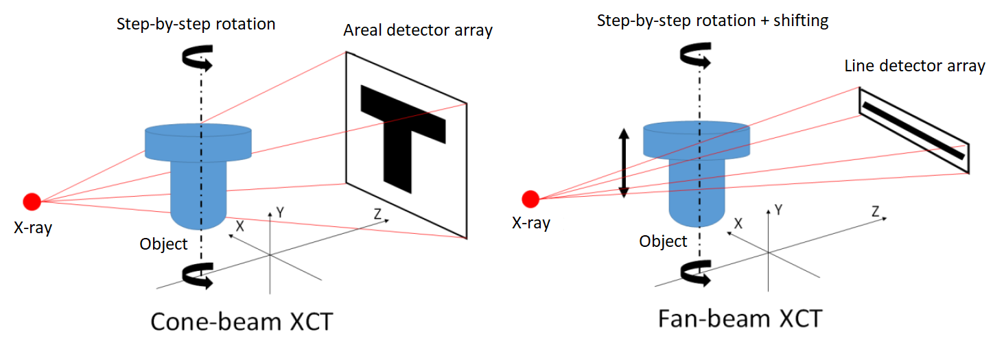
The residual of the X-ray, that is the weakened X-ray that passes through the material of the measured object, will be detected by an X-ray detector. The detected X-ray can be in the form of a 2D grayscale image (for cone-beam X-ray CT) or 1D grayscale profile (for fan-beam X-ray CT) as shown in figure 3 below.
The 2D images or 1D profile are captured at different angle rotation and/or different shifted location (for fan-beam type) of the measured object (rotated by a numerically controlled rotary table). Hence, a set of 2D images or 1D profile are recorded.
A mathematical calculation to reconstruct the 3D volume of the measured object is then performed by the software of the X-ray CT.
The reconstructed 3D volume is constituted by units of voxel (that is, in 2D, the voxel is called pixel). A unit voxel represents how large the material absorbs the X-ray energy travelling through it.
The energy decrease of the X-ray during a part travel inside the material is non-linear. This phenomenon is called beam hardening [4].
The measurement procedures
The measurement procedure for an X-ray CT are as follows (Figure 2):
- Part scanning and acquisition to obtain a set of 2D X-ray CT images.
- 3D volumetric reconstruction from the 2D X-ray images by using Radon transformation method.
- Surface determination from the reconstructed 3D volumetric model.
- Geometrical fitting to perform dimensional and geometrical measurements and the comparison between the reconstructed 3D model and nominal computer aided-design (CAD) model.
Step 1: Part scanning and acquisition to obtain a set of 2D X-ray CT images.
Two main X-ray CT configurations are presented in figure 3. The configurations are cone-beam and fan-beam X-ray CT [1]. Regardless the types of the configuration, the working principle of all X-ray CTs is the same.
The basic components of an X-ray CT are an X-ray source, rotational table, X-ray detector and a software to control the machine, to reconstruct the 3D volume of a measured part and to perform geometrical fitting for measurement calculations (figure 3).
From figure 3, the part scanning is performed at different rotation angle (plus different shifted position for fan-beam X-ray CT). From each scanning process, a 2D grayscale image (for cone-beam) or 1D grayscale profile (for fan-beam) is obtained at the X-ray detector.
This detector recorded the residual energy of the X-ray that pass through the material of the measured object. A set of large 2D grayscale images or 1D grayscale profile is recorded at the X-ray detector. These set of images or profiles are then processed in the next stage procedure or processing.
Step 2: 3D volumetric reconstruction from the 2D X-ray images by using Radon transformation method.
From the obtained set of 2D grayscale images or 1D profiles, mathematical calculations are performed to reconstruct the 3D volumetric model of the measured object.
The 3D volumetric reconstruction is based on a filtered-backpropagation method. This method is based on Radon transformation (linear integral transformation). This linear integral transformation is initially developed by J. Radon in 1917.
This model is an absorption model of materials when an X-ray passes through the materials with a specific coefficient of linear weakening $\mu$ and is formulated as:
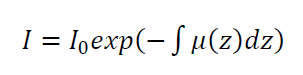
Where $I$ is the X-ray absorption amount of a material or medium. $I_{0}$ is the initial intensity of the X-ray that passes through the material or medium $\mu$ with distance $Z$.
Hence, the amount of $I$ at length $Z$ is then calculated as:
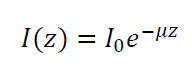
The voxel resolution of the reconstructed 3D volume depends on the voxel size at the X-ray detector, that are, the number of unit pixel at the X-ray image detector, the number of unit pixel in Y-direction, the number of angular position (rotational step resolution) in the X-ray scanning process, the number of 2D projection image taken per angular pose, the number of bin (binning) on the detector camera sensor and other aspects [1].
Step 3: Surface determination from the reconstructed 3D volumetric model.
After the 3D volumetric model of the measured object is reconstructed, the next step is edge determination to determine the surface of the measured object. This surface separates between the object material and air or with other different materials in the object (if any).
To determine the edge, a thresholding process is carried out. This thresholding is to determine the status of each unit voxel as either material or air.
The thresholding process can per performed in many different ways. This edge detection is a crucial step that determines the accuracy and traceability of dimensional and geometrical as well as surface texture measurements by using an X-ray CT.
The most common method to determine the thresholding value or limit is by ISO-50% method. This method is based on the histogram of the voxel values.
In general, the histogram of the voxel values has two (or more) peaks representing different materials and/or air. The ISO-50% method determine the threshold value as the middle point between the two peaks in the histogram [1] as shown in figure 2 above.
Step 4: Geometrical fitting to perform dimensional and geometrical measurements and the comparison between the reconstructed 3D model and nominal computer aided design (CAD) model.
The result of the edge detection is a 3D point cloud of the spatial coordinates of the points on the edge or the detected surface of the measured object.
From this point cloud, various types of mathematical geometrical fitting can be performed to determine dimensions or geometries to be measured.
Factors that affect the measurement results of X-ray CT are the variation of the X-ray source power, types of the X-ray, the material and shape of measured objects, temperature variation, scanning strategy (configuration) and operator effects.
READ MORE: Measurement uncertainty estimations: GUM method
X-ray CT for various measurement applications
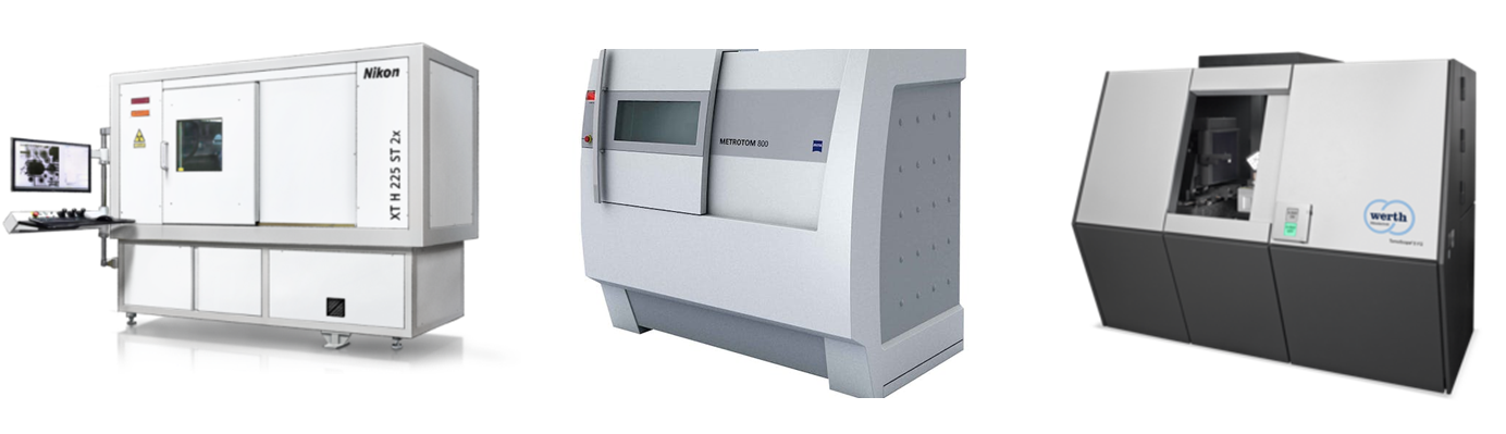
There are many commercial X-ray CT machines that are available in the market. Figure 4 shows some commercial X-ray CT machines that are often found in the market and industries, such as those that are manufactured by Nikon, Zeiss and Werth Messhtechnik.
For commercial X-ray CT machines used for industrial product measurements, very often, those machines use an X-ray source with 150 kV, 250 kV and 450 kV. The higher the source energy, the higher the penetration capability of the X-ray to pass high density materials, such as metals.
The measurement applications for X-ray CT are vast. X-ray CT can be used for the visualisation of a complex 3D part with internal features, the analysis of material defects, material characterisations, reverse engineering, dimensional and geometrical measurements, surface texture measurements, tolerance analysis, wall-thickness analysis and many more applications [3].
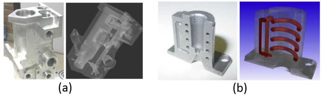
Especially for dimensional and geometrical measurements, X-ray CT is very useful to inspect internal defects of manufactured or mechanical parts. Figure 5 below shows some examples of the measurement of internal feature dimensions of a part by using an X-ray CT. The part is a mould made of aluminium with complex internal channels designed for internal cooling system. Many other applications can be found in [2].
READ MORE: Measurement system analysis: Gauge repeatability and reproducibility (Gauge R&R) test
The special characteristic of X-ray CT: Accuracy and traceability
Currently (at the time of writing this article), commercial X-ray CT machines have an accuracy level that is relatively lower than the accuracy level of conventional CMMs. However, the ability of X-ray CT to perform non-destructive measurements of the internal features of a part is an instrumental functionality that cannot be found on conventional CMMs.
Hence, research on how to verify and improve the accuracy of X-ray CT measurements as well as the traceability of X-ray CT measurement results are important and becomes a trend in geometrical metrology fields.
To verify or check the accuracy of X-ray CT, various types of reference (calibrated) artefacts have been proposed for various types of X-ray CT measurements. Figure 6 below shows various artefacts that have been proposed to verify the accuracy of X-ray CTs. There are also other artefacts that have been proposed other than those shown in figure 6.
In figure 6, some proposed reference artefacts are a collet cube artefact and pentagram sphere to check the accuracy for length measurements, cylindrical flute to check the accuracy for internal geometry measurements and complex geometry artefact to check the accuracy for complex geometry measurement such as gear measurements.
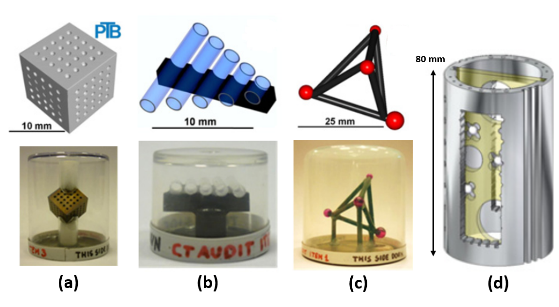
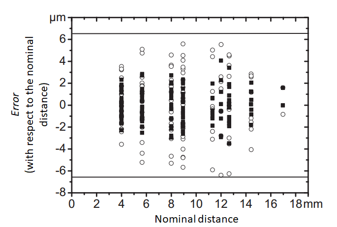
Figure 7 below shows one example of accuracy check/verification of an X-ray CT machine for a length measurement between two points or features. In figure 7, the accuracy of the X-ray CT used for length measurement between the centre of spheres is $\pm6 \mu m$ for length measurement up to $18mm$ [6].
X-ray CT measurements are a very complex measurement process. Uncertainty estimation of an X-ray CT measurement result is challenging to estimate. A proposal to estimate the uncertainty of X-ray CT measurements has been proposed by Dewulf et al [7].
The method proposed in [7] is based on a hypothesis that all measurement results are originally measured by voxel values. Hence, all aspects that affect the reconstruction of the voxels are considered as relevant uncertainty contributors. These contributors are then used in the estimation of X-ray CT measurement uncertainty.
The main uncertainty contributors are divided into two groups [7]:
- Uncertainty contributors from the size of the voxel (the resolution of the voxel). This uncertainty is contributed from a calibrated distance measurement, repeatability of the measurement of voxel size and probing error measured on a reference (calibrated) sphere.
- Uncertainty contributors from the numbers of voxel. This uncertainty is contributed from random variation of the measurement, edge offset both uniform and ununiform.
Until now, there have been many research and technology developments related to X-ray CT scan for part measurements. Hence, there have also been a significant increase in accuracy and efficiency of many X-ray CT machine and their measurement capabilities.
READ MORE: The history and introduction of CMM: the inseparable relation between CMM and GD&T
Conclusion
In this post, the history, working principle and measurement procedures, measurement applications and characteristics (in term of accuracy and traceability) of X-ray CT have been discussed. The basic working principle of X-ray CT system has been around from decades ago from the results of the invention of X-ray by Wilhelm Röntgen in 1985 and the invention of Radon transformation method by J. radon in 1917.
The instrumental capability of X-ray CT is the non-destructive measurement of complex geometry internal features of parts. In addition, a unique characteristic of X-ray CT is that the measurement time is not affected by the number of features to measures. Both small and large number of features can be measures approximately with approximately the same amount of scanning time.
The applications of X-ray CT are vast, ranging from 3D model visualisation to inspect internal (also external) features to dimensional, geometrical and surface texture measurement of industrial parts.
Currently, the accuracy of measurement and the traceability of measurement results of X-ray CT are relatively lower than conventional CMMs. However, many research have been done and are being performed to improve the accuracy of X-ray CT measurement as well as to establish the traceability of X-ray CT measurement results.
Reference
[1] Kruth, J.P., Bartscher, M., Carmignato, S., Schmitt, R., De Chiffre, L. and Weckenmann, A., 2011. Computed tomography for dimensional metrology. CIRP annals, 60(2), pp.821-842.
[2] Carmignato, S., Dewulf, W. and Leach, R. eds., 2018. Industrial X-ray computed tomography (Vol. 10, pp. 978-3). Cham: Springer International Publishing.
[3] De Chiffre, L., Carmignato, S., Kruth, J.P., Schmitt, R. and Weckenmann, A., 2014. Industrial applications of computed tomography. CIRP annals, 63(2), pp.655-677.
[4] Dewulf, W., Tan, Y. and Kiekens, K., 2012. Sense and non-sense of beam hardening correction in CT metrology. CIRP annals, 61(1), pp.495-498.
[5] Carmignato S, Pierobon A 2010 International comparison of CT systems for dimensional metrology: The “CT Audit” Project. Industrielle Computertomografie, Tagung, FH Wels, Austria.
[6] Bartscher, M., Hilpert, U., Goebbels, J. and Weidemann, G., 2007. Enhancement and proof of accuracy of industrial computed tomography (CT) measurements. CIRP annals, 56(1), pp.495-498.
[7] Dewulf, W., Kiekens, K., Tan, Y., Welkenhuyzen, F. and Kruth, J.P., 2013. Uncertainty determination and quantification for dimensional measurements with industrial computed tomography. CIRP Annals, 62(1), pp.535-538.
You may find some interesting items by shopping here.